Looks like you don't have ESC button on your device
Download IronCAD DCS
Choose one of the following options
trial versionHas a license
Looks like you don't have ESC button on your device
Choose one of the following options
trial versionHas a license

Emil Rindell

Jonas Bryntesson

Henrik Andersson
2020-01-01
Emil Rindell
Jonas Bryntesson
Henrik Andersson
2020-01-01
The anchor point in IRONCAD is the permanent property that determines where in a 3D scene an object is located and the orientation of the object around the axes of the XYZ space. Permanent in the sense that it is always there and cannot be removed, but mobile nonetheless! You can get by pretty well in IRONCAD without knowing that the anchor point exists or how it works. You simply don't need to handle it at all to still have control over where in space one or more objects are.
But some simple rules are still good to know as they make it easier to deal with some of the situations you sometimes find yourself in. Many people notice after a period of use that "that needle" can be good to understand. Our basic training material covers Anchor Point and Catalog Management, which you can find on our Swedish IronCAD Academy, from exercise 56 to 61:
Watch a movie about catalog management in IRONCAD
Objects in IRONCAD's 3D scene are handled by a right-oriented Cartesian coordinate system, just like the vast majority of CAD/CAM systems and manufacturing NC machines on the market today.
The reason why many people experience a "freedom" in positioning objects in IRONCAD is because the basic principle is as simple as it is ingenious and obvious. Everything is based on an XYZ coordinate in 3D space.
Unlike traditional "fully parametric" 3D CAD systems, there is no need to define "individual coordinate systems" per object in the 3D environment, which can be more or less time consuming in different systems. Instead, a corresponding unique "insertion point per object" or "local coordinate system" is created fully automatically. It is called in IRONCAD the Anchor Point and can be managed with various settings and tools.
Just like in traditional 3D CAD systems, you can have objects "free" or "locked" in 3D space. The major difference with other systems is that in IRONCAD you have an additional "mode" - "precision control of position and orientation" through the TriBall tool.
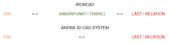
IRONCAD does not require you to impose locks or constraints on other objects in space in order to have control. With TriBall, you can freely move objects relative to the coordinate system with full precision. An "object" is a Part, Assembly or Feature (e.g. Extrude / Spin / Sweep / Loft ) in the 3D scene. But you can also move other "3D scene specific objects" such as cameras, lights, textures/decals and much more.
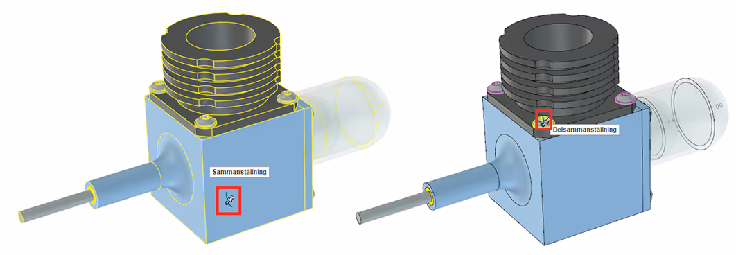
The anchor point is automatically created on any object that the system requires in order to handle it in the 3D scene coordinate system. Here we have, for example, assembly (top-level), Part assembly, Part and Feature;

When you drag and drop an item out of a catalog, it is "really" the Anchor Point you are dragging out! Even if it's geometry you're looking at and thinking about, it's the Anchor Point you're working with. Usually it is only when you know about it, that it is something you actually see. The anchor point always ends up at the 0-point of the coordinate system in a new empty 3D scene, no matter where in space you drag the icon from the catalog.
In a 3D scene with existing objects, it ends up on the exact "voxel" (volume pixel) you drop it. That's why you usually fire the TriBall and move the object (together with the Anchor Point) immediately after dropping it from the catalog. Usually there is no need to move the anchor point itself, as it is the geometry you are working with first and foremost.
The anchor point has 4 properties that are either set automatically depending on where or what you drop it on, or adjusted afterwards. It controls how or if the object takes into account other objects in the 3D scene. By right-clicking on the Anchor Point you can access 4 properties:

The bottom setting is also the default mode and is called Disallow Drag. This means that the Anchor Point cannot be moved simply by dragging it or its objects with the mouse pointer. Tools such as TriBall or Smart Dimensions are now required. There is a pin at the center of the Anchor Point to indicate this "locked position" visually.
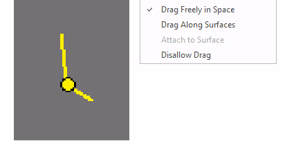
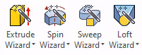
The Drag Freely in Space setting allows you to drag around the Anchor Point or its objects freely in 3D space with the mouse pointer. There is no precision and therefore this setting is generally not recommended. However, Drag Freely in Space is the Anchor Point's default mode for new parts created via the Extrude Wizard, Spin Wizard, Sweep Wizard and Loft Wizard tools. Therefore, it is good to adjust the setting afterwards on these new parts.
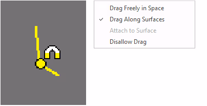
The Drag Along Surfaces setting allows you to "surf" (drag the object with the mouse pointer) along the surfaces of different objects within the same level of the structure (objects under the same summary in the tree). There is a magnet at the center of the Anchor Point to indicate this visually. You can, if a feature is selected, use the [Shift] key to snap to existing geometry to find e.g. tangent properties between a flat and cylindrical surface.

The Attach to Surface setting is only shown on the Anchor Point belonging to a feature. It allows you to "surf" (drag the object with the mouse pointer) along surfaces and edges within the same part. At the center of the Anchor Point, a magnet with two lightning bolts is displayed to indicate this visually. Again, the [Shift] key works to snap to existing geometry.
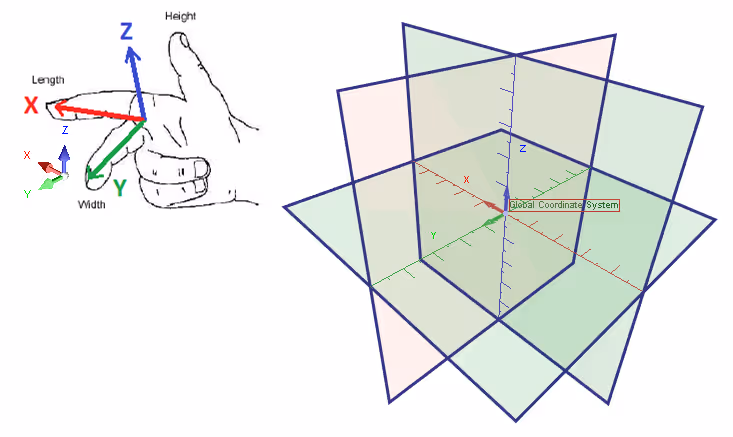
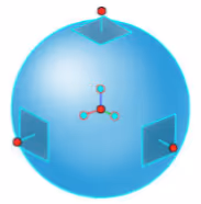
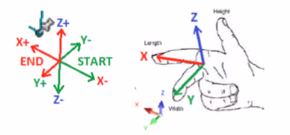
The anchor point (red box in the picture) has its own built-in coordinate system with a positive and negative "XYZ direction". As the visual symbol is relatively small on the screen, it can be difficult to see in which direction it is currently pointing.
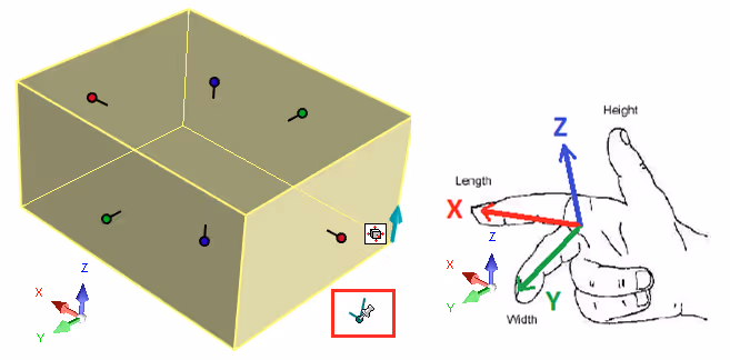
The long axis corresponds to positive Z direction, or think equivalent to the thumb of the right hand. The short axis corresponds to positive X direction, or the index finger of the right hand. This leaves the positive Y direction which lacks a visual shape and therefore may require the visual image above with the middle finger of the right hand as the positive Y direction. The anchor point can therefore have a completely different orientation than the fixed coordinate system of the 3D scene. It also does not have to follow the contours and edges of the geometry it belongs to, although this is often recommended.
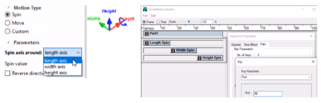
When animating in IRONCAD , the Anchor Point is moved and takes the object it belongs to with it. It is then useful to know the three directional and rotational names around the three axes.
X (red) is called Length (see picture below left) for longitudinal movement and Tilt for rotation.
Y (green) is called Width for longitudinal movement and Roll for rotation (see image below right).
Z (blue) is called Height for longitudinal movement and Pan for rotation.
Learn more about animation in IRONCAD via our basic training material at IronCAD Academy, exercises 66-67:
Watch a movie about video animation in IRONCAD
Since the anchor point in IRONCAD is mobile, a tool is needed to handle this with precision - that precision tool is the TriBall.
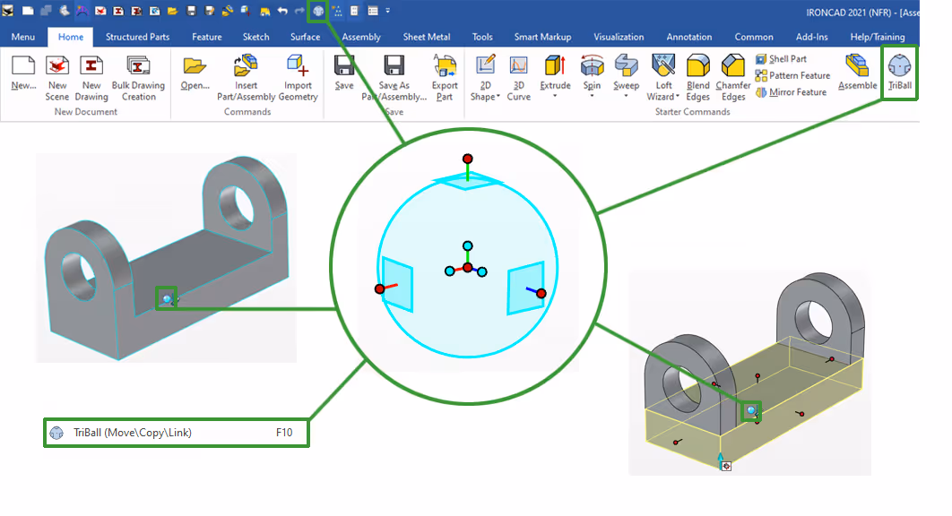
Activate the TriBall tool:
The icon for switching the TriBall on and off can be found in several places in IRONCAD. For example, in the Quick Access Toolbar and under the Home tab. TriBall is also available via right-click, and as an icon at the Anchor Point, on Intellishapes, Parts and Assemblies, as shown in the image below.
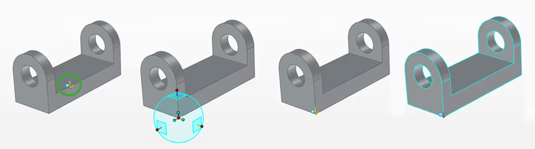
To move the Anchor Point itself with the TriBall, you must first click on it. The colour will then change from green to yellow and the blue edge lines of the pair will be turned off. When you activate the TriBall, it is now the Anchor Point that is moved and rotated. For example, if you would rather have the "zero point" of the part in a corner instead of in the middle of the part.
Learn more about how TriBall works via our basic training material at IronCAD Academy, exercises 5-7:
Watch a movie about TriBall in IRONCAD
By placing dimensions (Smart Dimensions) you can control the position of objects in the 3D scene, including the Anchor Point. It is not very common (except for some parameter control) to place dimensions from just the Anchor Point. Position controlling dimensions are usually placed between objects in some combination of e.g. "hole - block", "part - part" or "smst - part" etc.
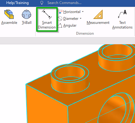
To attach a Smart Dimension to an Anchor Point, you must first select the object (feature, part or assembly), then hold down the [Ctrl] key. The anchor point will then have a cyan blue dot to which the dimension is attached, no matter where on the selected object you click.

For Patterns created with TriBall it is also required to have a special setting enabled, otherwise the measure is linked to the object (feature, part or assembly) instead of to the Anchor Point of the pattern itself.
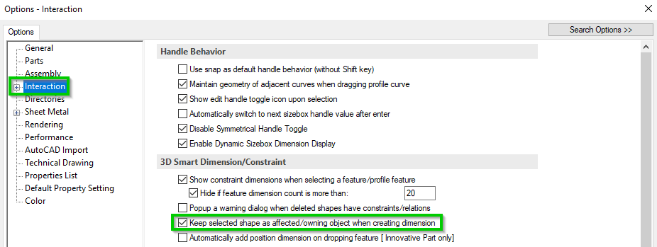
The setting is found under Interaction and is called Keep selected shape as affected/owning object when creating dimension. That is, "let the selected object own or be controlled by the dimension being created". Without this setting enabled, it is not possible to set dimensions to the Anchor Point for Patterns.
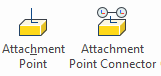
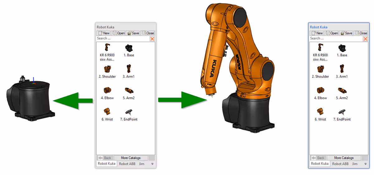
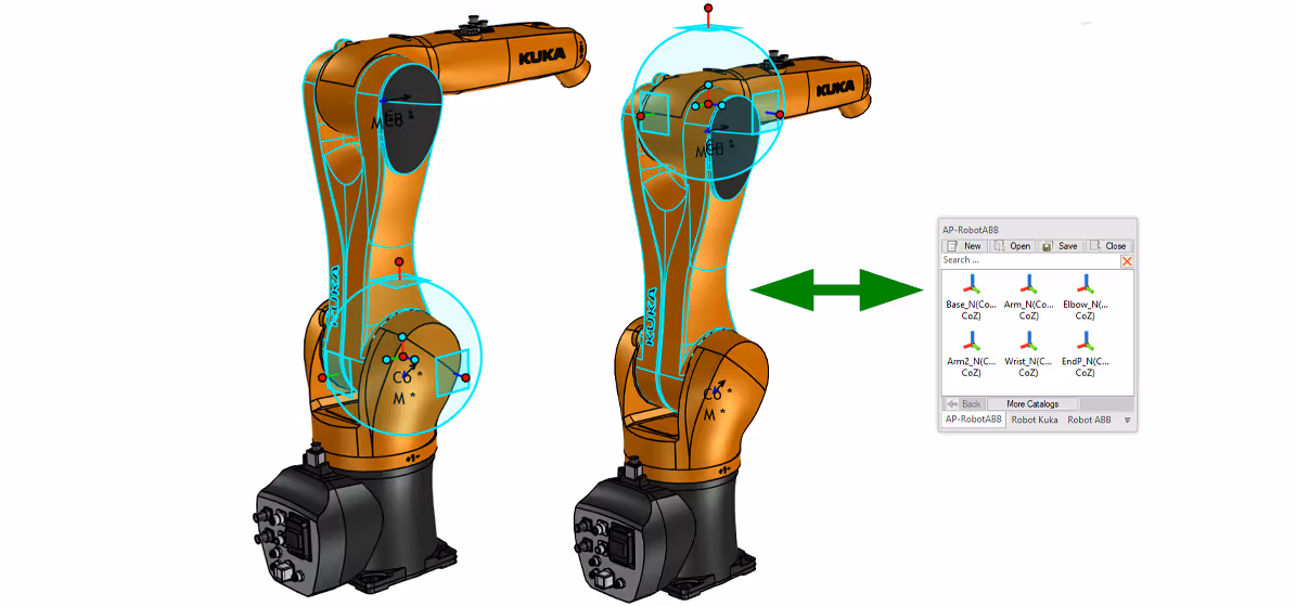
Attachment Points allow you to add more points per object. These attachment points can also detect other attachment points with similar properties, when dropped from a directory onto an object with similar attachment points. This allows you to quickly and easily assemble, for example, a robot or a frame for a storage tent.
The tool to create these is available under the Tools tab, Intelligence icon group. It is also possible to create attachment points via the right-click menu on the TriBall centre handle:

The main difference between the two ways of creating attachment points is that the one created with TriBall does not automatically become associated with the geometry it is placed on, as it does when you click it out with the tool or drag an attachment point from a catalog. Because a point or surface is highlighted in green, it also becomes associated with that particular point or surface. The TriBall activated on a part or smst containing attachment points can be easily moved between existing attachment points with the [TAB] key. Attachment points can also be easily reused via catalogs. Just make sure to select the right item before dragging the anchor point out of the catalog. If necessary, adjust its position with TriBall.
Learn more about managing attachment points in our Layout training material at IronCAD Academy (exercises 6-8):
Watch the training movie about Layout in IRONCAD
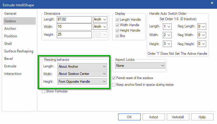
Under Intellishape Properties you can manage 3 different basic rules for how a Sizebox L, W and Z handle should work. Also here the Anchor point is involved. Under Resizing behavior you can choose that changes in a certain direction can only happen "from" the Anchor point - About Anchor. For example, a Cylinder or Sphere shape. In these two cases, however, it works predictably only if the Anchor point is really in the center of the shape. The other two options are; from the center of the Sizebox - About Sizebox Center (mostly used when scaling a part/smst) or from the opposite handle - From Opposite Handle (e.g. a Block or Cylinder Opposite Handle shape).
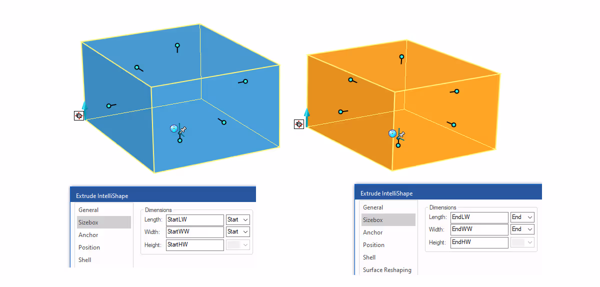
Locking the change of the Sizebox handle relative to the position and orientation of the Anchor Point is especially common when parameterizing the Sizebox dimension values. This can be done at Assembly, Part or Feature level. The direction of change is by default controlled by the position and orientation of the Anchor Point.
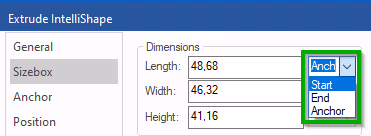
Start - means opposite direction to the visible positive axes of the anchor point.
End - means the same direction as the visible positive axes of the Anchor Point.
Anchor - means symmetrically about the center of the anchor point (default position).
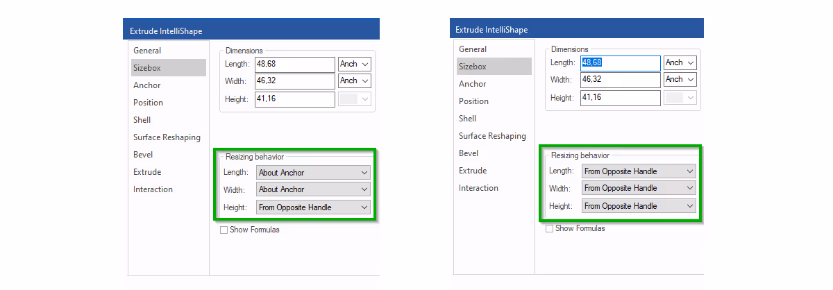
By linking a parameter to a Sizebox handle, you can control the shape of the model via a parameter table. By default, it is controlled relative to the position and orientation of the anchor point. However, by changing from Anchor to Start or End, you control the property only relative to the orientation of the Anchor point.
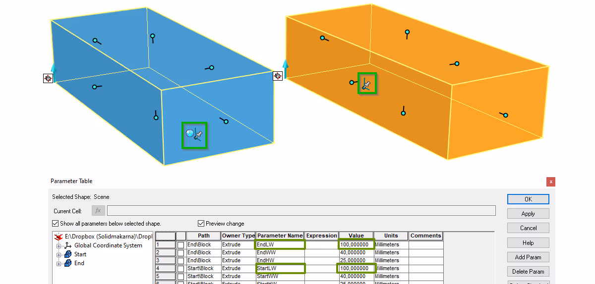
When the same parameter is changed on the example models above (the Length parameter ***LW, linked to the Length handle), the dimension is adjusted in the direction the Sizebox settings are set to. The blue model is adjusted in the Start direction of the Anchor Point, while the orange one is adjusted in the End direction. Otherwise, the models are identical.
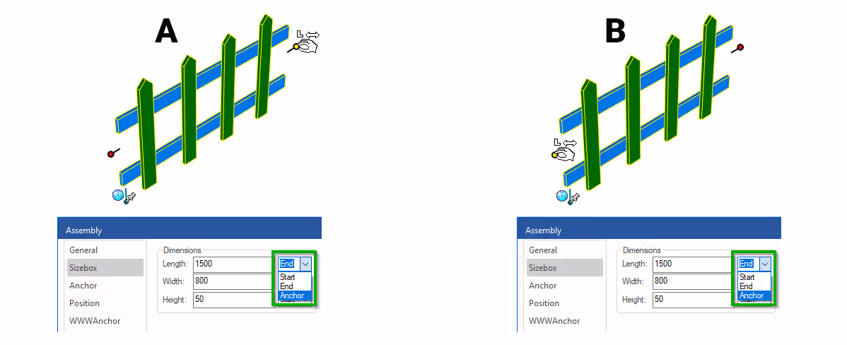
Compare also with a parametrically controlled fence assembly. The fence below may only be extended in one direction of the L-handle, now by pulling it. There are 2 different solutions for this;
A) Anchor - The anchor point is placed on the opposite side of the handle to be pulled. This counteracts the possibility of pulling the L-handle on the same side as the Anchor Point. The fence can now only be extended in one direction -> opposite side of the Anchor Point.
B) Start/End - The fence should be extendable in both directions of the L-handle or the anchor point cannot/may not be placed at one end of a model controlled by parameters for some reason, it may have to be placed a certain distance from one edge and/or a certain distance up from the bottom edge instead. Then you can no longer control the handle relative to the position of the anchor point, now only its orientation should control. In addition, the anchor point follows the change and maintains its relative position within the object's Sizebox.
Answer: Here we publish tips, guides, news and solutions for those who work with IRONCAD and Design Data Manager (DDM). The blog covers everything from basic functions to advanced workflows, helping you to optimize your design work. You'll find examples of smart shortcuts, practical instructions, solutions to common problems, and best practices for product design, mechanical design, and product data management.
Answer: Our guides and tips are designed for both beginners and experienced CAD users. They are aimed at designers, engineers and project managers who want to work more efficiently with IRONCAD and DDM, improve the design process, reduce mistakes and save time in product development.
Answer: We regularly publish new articles when the software is updated, when new features are introduced, or when our users ask for solutions to specific problems. The blog is therefore a reliable source for keeping up to date and getting tips that make everyday CAD work easier.
Answer: Many of our instructions and tips work in multiple versions, but we clearly indicate if an article applies to a specific version. We strive to make the content useful for older versions as well, and also provide recommendations on how to adapt workflows to the version you are using.
Answer: Absolutely! If you can't find the solution in the blog, you can contact our technical support via solidmakarna.support. Our experts will help you with everything from installation and configuration to advanced features in IRONCAD and DDM, so you can solve problems quickly and efficiently.
Answer: Yes! We appreciate suggestions from our users. If you have questions, tips or want us to address a specific issue in IRONCAD or DDM , please contact us via our contact form and we will prioritize relevant topics in future posts.
Answer: The blog contains, among other things:
Practical step-by-step guides to help you use IRONCAD and DDM more effectively.
Productivity and workflow tips for faster design and construction.
Solutions to common problems encountered by users in CAD programs.
Updates and news on new features, versions and improvements.
Best practices for data management and project organization in DDM.
Answer: All tips and guides are directly applicable in daily work. For example, you can use shortcuts and smart features in IRONCAD to speed up modeling, structure files better in Design Data Manager, or follow our step-by-step solutions for specific problems that often come up in design projects.
Answer: We strive to ensure that all guides and tips are relevant to the latest versions of IRONCAD and DDM. We also clearly mark when a post applies to an older version, so you always know if the instruction is directly applicable to your system.
Answer: Yes! Many of our users share the articles with colleagues and use them as internal training materials. The blog is a great complement to formal training and helps teams learn features faster, avoid mistakes, and standardize workflows in IRONCAD and DDM.