Looks like you don't have ESC button on your device
Choose one of the following options
trial versionHas a license

Looks like you don't have ESC button on your device
Choose one of the following options
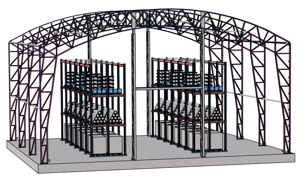
trial versionHas a licenseIRONCAD is a comprehensive 3D CAD program. In the layout phase, it is used to place imported machines, robots, and conveyor systems within the building, with tens of thousands of parts in a single file, and to provide floor plans, renderings, and models to the customer.
Over 1000+ satisfied customers



Tens of thousands of parts in a single file
The building as an IFC or DWG file
Machines from all CAD systems
IRONCAD IRONCAD is a 3D CAD program for industrial design, ranging from machinery and sheet metal to layouts and fixtures. What sets apart from traditional CAD systems is the freedom of choice: you decide for yourself how to model. Design freely using drag-and-drop and TriBall, add constraints and parametric dimensions only where they’re needed, and modify imported geometry directly without a history tree. These methods can be combined within the same , and the entire assembly is contained in a single file. This page shows how companies that design factories and production lines use it. part
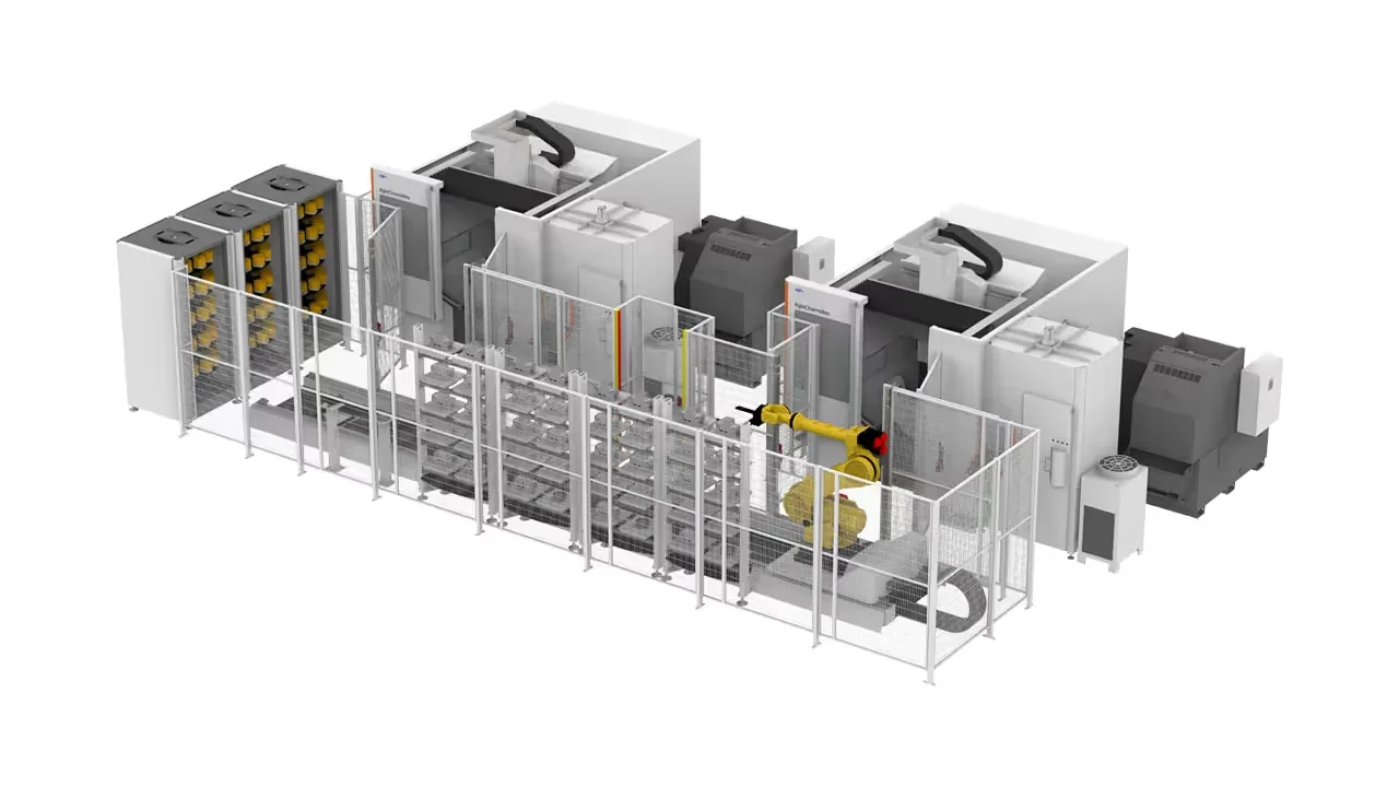
The video is System 3R’s own presentation of the company, part of GF Machining Solutions: robots on rails that serve CNC mills and lathes so that the machines run without interruption. The layouts for customer quotes—featuring fences, rails, robots, and imported CNC machines—are designed in IRONCAD by automation experts on three continents. The video is in English. Would you like to see what your next layout might look like in IRONCAD?
Book a demo and we’ll show you!
You choose the method for each section, not for the entire program.
All three work in the same file, and they can be mixed within a single layout.
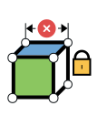
For fences, rails, and mezzanine floors in modules. Lock the spacing, height, and compartment width using constraints, and the next length will be recalculated without you having to redraw it.
MOST POPULAR
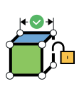
The standard method for layout. Drag in machines, fences, and conveyor belts; position them using TriBall; and move them freely as the flow changes. The parts remain where you dropped them, without hundreds of thousands of constraints.
For suppliers' STEP files of machines and robots. Select an area and drag, trim away what isn't visible, and add fasteners. No history is required.
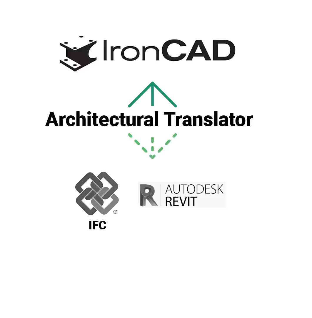
The building is imported from the architect as an IFC or Revit file with the Architectural Translator, with walls, columns, and floor plans already in place. A DWG floor plan is opened in DRAFT and used as the basis for the 3D model.
Once the layout is complete, it can be exported back as an IFC file to the construction designer.
Milling machines, lathes, robots, and conveyor systems are imported as STEP files or via Translator from SolidWorks, Inventor, and CATIA. The machine is placed in the layout with its detail intact and can be simplified or cut without altering the original.
System 3R builds its robot cells as follows: with its own guardrails, rails, and robots arranged around the customer’s CNC machines.
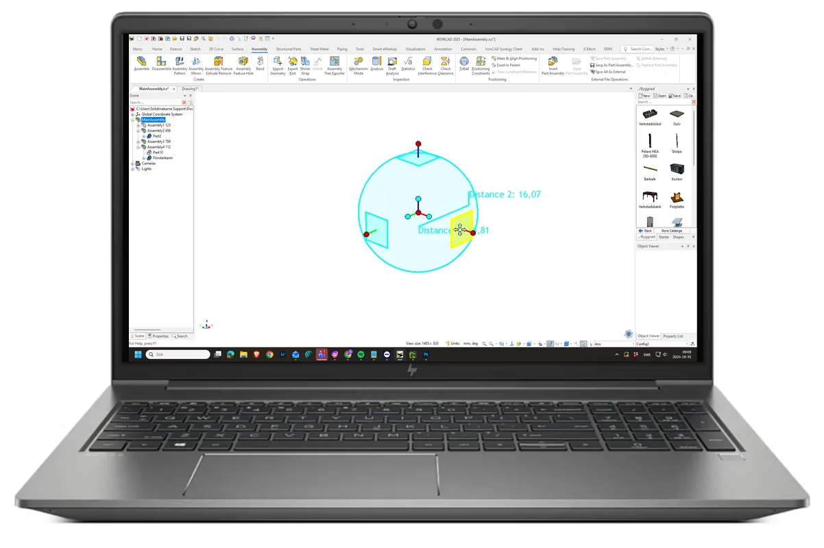
The machine is pulled in, aligned with the row of columns, and moved using TriBall until the flow is correct. Distance, reach, and forklift aisles are checked directly in the model, and an entire cell is moved as a single unit.
No constraints to manage. The parts stay exactly where you want them.
The entire facility is arranged in a single file. Imported machines that are not modified are simplified using Shrinkwrap, so that the model remains fast to open, save, and view.
Höga Kusten Teknikresurs designs sawmill layouts consisting of several hundred thousand parts in this way, using the customer's 2D drawings as a basis.
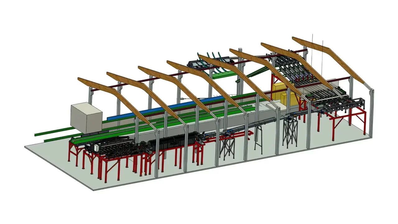
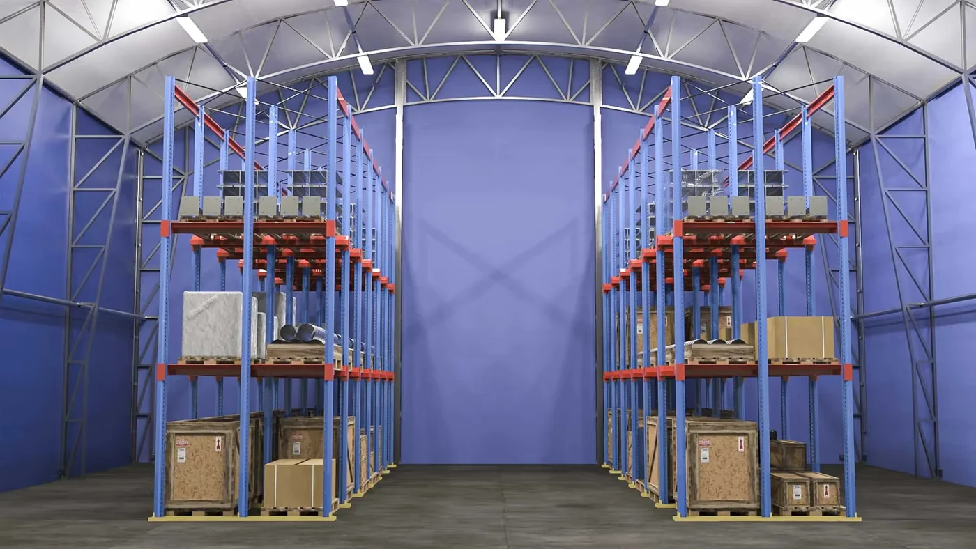
Frames, pallet racks, fences, rails, and mezzanine floors are listed in separate catalogs and are imported as modules. PMH International assesses how the customer’s needs can be accommodated within a given space and presents the solution as a rendering.
Cranes and material-handling equipment will be installed in the customer's existing building in the same manner.
ICD creates floor plans with dimensions, cross-sections, and a bill of materials for machines and modules directly from the layout. DRAFT features a traditional 2D interface similar to AutoCAD and can open and save the customer’s DWG files.
Both follow the procedure for moving a machine. Please submit the floor plan as a PDF or DWG file.
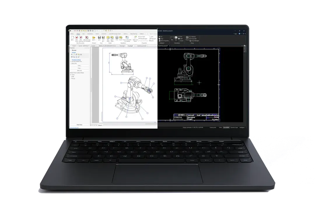
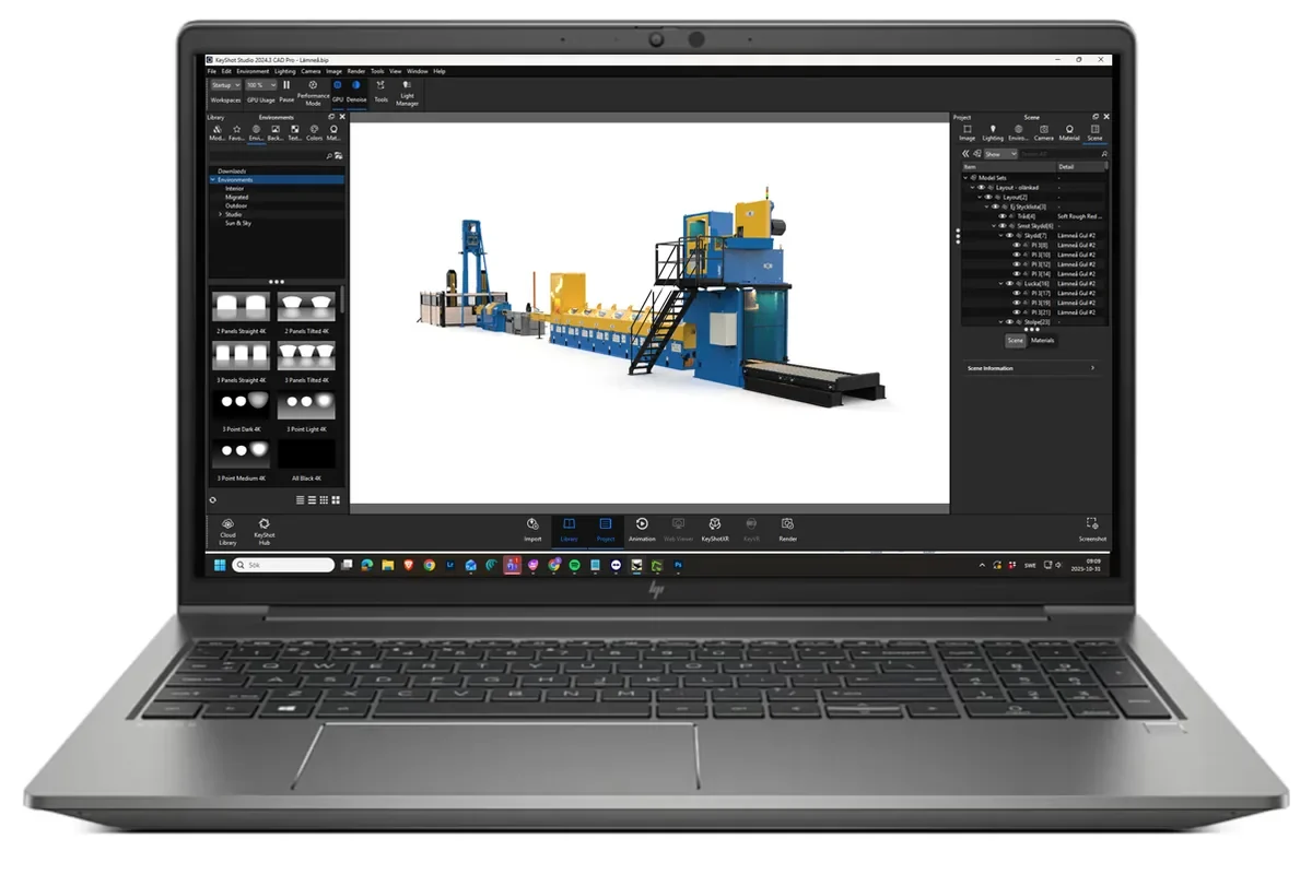
Render the layout using KeyShot to create quotes and presentations, directly from the model. The customer opens the 3D model in the free viewer at COMPOSE, rotates it, takes measurements, and adds comments—all without a CAD license.
The drawings for installers and subcontractors are shared via Design Data Manager, so that everyone builds according to the same revision.
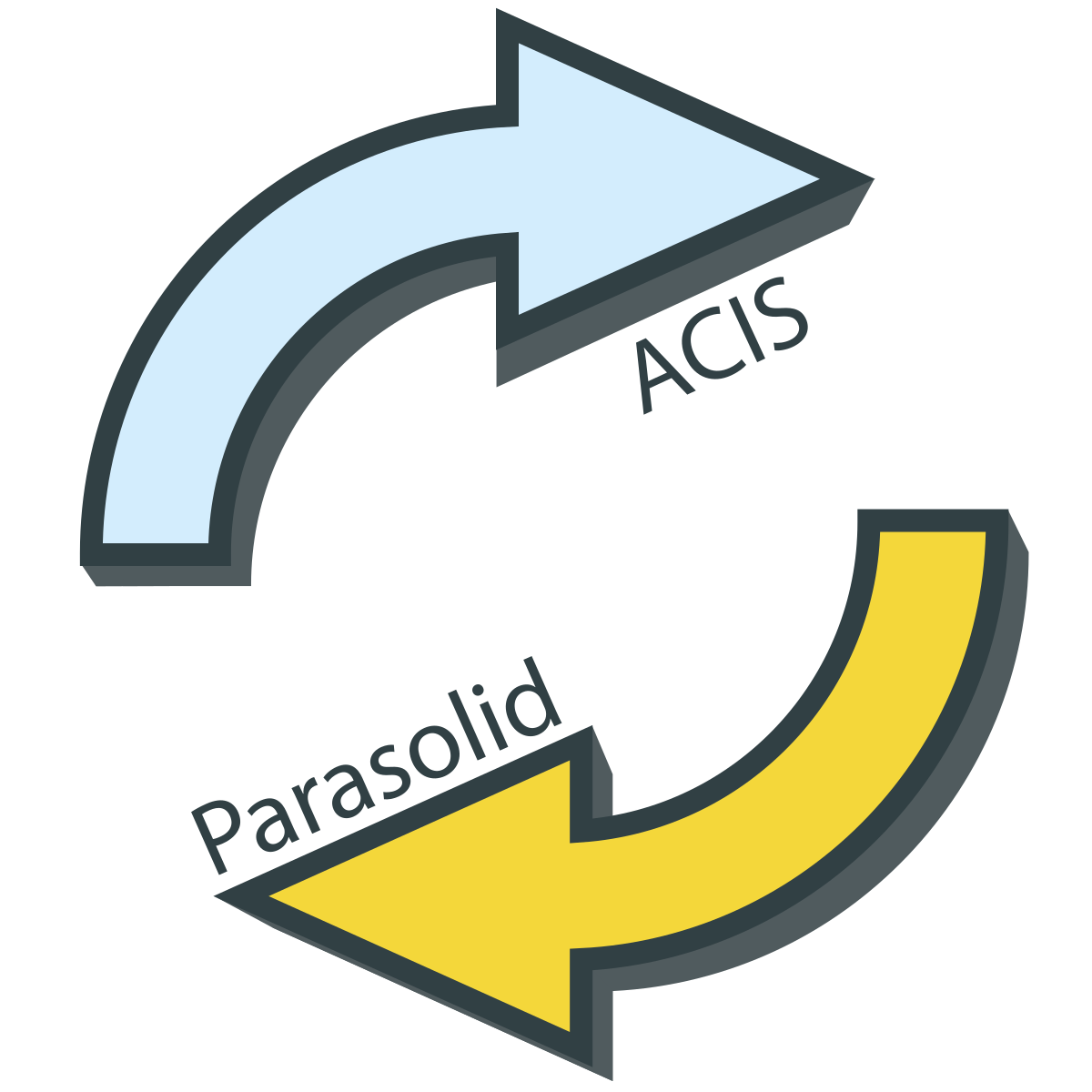
Imported models from all CAD systems into the same scene, without conversion.
The floor plan is sketched freely on the DWG file. Use parameters whenever you want—they're not mandatory.

Fences, rails, a mezzanine level, and custom standard cells with drag-and-drop functionality.

Move, align, and copy machines and cells with precision, without constraints.



Robotic automation for prefabricated homes, delivered to forty countries on four continents. Designs, drawings, and documentation are managed in Design Data Manager and shared with installers and subcontractors.

“Above all, we value the simple user interface that makes it easy to organize and find data, as well as the powerful web interface that makes it easy to share drawings internally with our installers and externally with our subcontractors.”
Mikael Adolfsson, Engineering Department Manager, Randek Robotics AB
Portal machines for prefabricated building components from Halmstad, which nail, glue, saw, and mill. Each factory has its own layout, so the machines are customized to fit the customer’s production line at IRONCAD.

“We are very pleased with how IRONCAD meets our design needs and also with the support we receive from Solidmakarna.”
Arne Alvarsson, Triweco AB
A full-service provider in machine design and wood processing since 1993, with our own sawmill machinery for customers throughout Europe. Layouts for lumber handling are created in IRONCAD , with several hundred thousand parts in a single file.
“The program offers more flexibility and is well-suited for testing various alternative solutions. We start with the customer’s needs and test different options until we find the best solution.”
Stefan Andersson, Höga Kusten Teknikresurs AB
Robotic operation of CNC milling machines and lathes, with robots on rails moving between the machines. 2D and 3D layouts for budget quotes are created in IRONCAD by automation experts in Europe, the U.S., and Asia.
“IRONCAD is easy to use and learn, and we have internally trained several automation experts across all continents at IRONCAD. This enables us to efficiently and quickly use IRONCAD to design 2D and 3D layouts when preparing budget quotes for our customers.”
Magnus Bobeck, System 3R (GF Machining Solutions)

Entire assemblies consisting of tens of thousands of parts are stored in a single file. Imported machines retain their level of detail, and performance is maintained through simplified representations of elements that do not change.
Yes. With Architectural Translator , IFC and Revit files—including walls, columns, and floor plans—are imported, and the layout can be exported back as an IFC file. DWG floor plans open directly in DRAFT and are used as a reference.
Yes. STEP, IGES, and Parasolid files open immediately, and with " Translator ," SolidWorks, Inventor, CATIA, and NX files also open. The part is placed in the layout and can be simplified or cut without altering the original.
Render using KeyShot for quotes and presentations, or send the model so the customer can open it in the free viewer at COMPOSE, rotate it, take measurements, and add comments. Floor plans with dimensions and a bill of materials are provided in 2D or DWG format.
The automation side involves designing the robot cell itself, including grippers and fixtures. Layout involves positioning machines, cells, and conveyor lines within the building and ensuring that the entire system functions properly. Many customers handle both aspects at IRONCAD.
With Design Data Manager, every layout, machine, and drawing is assigned a part number, revision, and searchable properties, and the drawings are shared with installers and subcontractors via the web interface. Randek Robotics chose DDM for precisely that reason.
Full version for 30 days, free of charge. Swedish support and training from Solidmakarna.

30-day full version of IRONCAD . No credit card information required, no obligation to purchase.

Install the software, open your own files, and follow the setup wizard in the IronCAD Academy.

We'll show you how IRONCAD fits your specific production needs—in just half an hour.

A 2 + 2-day instructor-led introductory course, or self-paced study. Course instructors who design their own projects in IRONCAD.