Looks like you don't have ESC button on your device
Download IronCAD DCS
Choose one of the following options
trial versionHas a license
Looks like you don't have ESC button on your device
Choose one of the following options
trial versionHas a license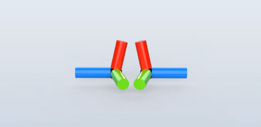

Emil Rindell

Jonas Bryntesson

Henrik Andersson
2020-01-01
Emil Rindell
Jonas Bryntesson
Henrik Andersson
2020-01-01
An Attachment Point (also AP or magnetic attach point) is a type of coordinate point attached to an object in the 3D scene (e.g. a Feature, Part or Assembly) that also has a counterpart that it wants to find, when the object it belongs to is adjacent to another object with a corresponding AP. The type of object itself to which an attachment point is attached does not matter.

These attachment points are very useful for several purposes, but perhaps most importantly for layout work where you can easily get it to fall into place automatically. All you have to do is drag-and-drop a prepared object into the 3D scene from a catalog, near an existing snap point and it will end up in the right place with the right orientation automatically!
Attachment Points allow you to add locations/points on an object that can sense other objects with similar properties. This is mainly done when they are dropped from a catalog onto an object with just similar attachment points. In this way, you can quickly and easily assemble, for example, a robot or a frame for a storage tent.

You can also directly grab an object's attachment point and drag and drop it onto another visible attachment point in the 3D scene. They don't have to have the same properties, but still stick.

The tool to create these is available under the Tools tab, Intelligence icon group. It is also possible to create attachment points via the right-click menu on the TriBall centre handle:

The main difference between the two ways of creating attachment points is that the one created with TriBall does not automatically become associative with the geometry it is placed on, as it does when you click it out with the tool or drag an attachment point from a catalog. Since a vertex point or surface lights up in green, it also becomes associative to that particular vertex point or surface.

An attachment point requires no special properties to work via drag-and-drop between each other directly in the 3D scene. However, if you want to get the automatic placement feature when dragging from a catalog, you need to specify some basic properties of the attachment point.
Select and right-click on the attachment point, choose Set Name and Behaviors.

A new window will appear showing all the properties that can be connected with attachment points. To begin with, the name User Name is the single most important property.

The name controls whether the attachment point should be able to find other attachment points within the same object it is dropped on, when it is dragged out of a catalog. It is then limited to only find those with the same name, the others are ignored. You can further restrict how attachment points find each other by the Type property which specifies whether the attachment point is a Male, Female, Neutral or No paired. An attachment point of type Male is only compatible with another attachment point of type Female and vice versa.

The Neutral type finds each other in both directions, hence the name. The No Paired type is the basic property.

An AP is moved and oriented by first highlighting it so that it glows yellow, then TriBall is activated. When the TriBall is activated on a part or assembly containing attachment points, it can be easily moved between existing attachment points via the [TAB] key. In this way, several predefined positions can be used to move the TriBall between them in a smooth way.

Attachment points can also be easily reused with catalogs. Hold down the right mouse button to drag a selected attachment point to a catalog. When dropping an attachment point from a catalog, just make sure to select the correct item first. A surface, edge or vertex point will light up in green. Marking an object before releasing it from a catalog is important in other contexts as well in IRONCAD. Adjust its position and orientation with the TriBall if necessary.

To delete APs, right-click on them and select Delete AP.

An attachment point dropped from a catalog onto an object that has a corresponding attachment point will automatically be attached to the other. They will then have the mutual orientation where the blue Z-axes will point in the opposite direction while the red X-axes will point in the same direction.

Each *.ics file has background settings to control the visibility of the attachment points in the 3D scene. Therefore, you can also control this in the ICS template by right-clicking in the background and using the Show... option.
Attachment Points - shows AP's all the time.
Hide Attachment Points on Selection - Turns off AP's when items are selected.

Answer: Here we publish tips, guides, news and solutions for those who work with IRONCAD and Design Data Manager (DDM). The blog covers everything from basic functions to advanced workflows, helping you to optimize your design work. You'll find examples of smart shortcuts, practical instructions, solutions to common problems, and best practices for product design, mechanical design, and product data management.
Answer: Our guides and tips are designed for both beginners and experienced CAD users. They are aimed at designers, engineers and project managers who want to work more efficiently with IRONCAD and DDM, improve the design process, reduce mistakes and save time in product development.
Answer: We regularly publish new articles when the software is updated, when new features are introduced, or when our users ask for solutions to specific problems. The blog is therefore a reliable source for keeping up to date and getting tips that make everyday CAD work easier.
Answer: Many of our instructions and tips work in multiple versions, but we clearly indicate if an article applies to a specific version. We strive to make the content useful for older versions as well, and also provide recommendations on how to adapt workflows to the version you are using.
Answer: Absolutely! If you can't find the solution in the blog, you can contact our technical support via solidmakarna.support. Our experts will help you with everything from installation and configuration to advanced features in IRONCAD and DDM, so you can solve problems quickly and efficiently.
Answer: Yes! We appreciate suggestions from our users. If you have questions, tips or want us to address a specific issue in IRONCAD or DDM , please contact us via our contact form and we will prioritize relevant topics in future posts.
Answer: The blog contains, among other things:
Practical step-by-step guides to help you use IRONCAD and DDM more effectively.
Productivity and workflow tips for faster design and construction.
Solutions to common problems encountered by users in CAD programs.
Updates and news on new features, versions and improvements.
Best practices for data management and project organization in DDM.
Answer: All tips and guides are directly applicable in daily work. For example, you can use shortcuts and smart features in IRONCAD to speed up modeling, structure files better in Design Data Manager, or follow our step-by-step solutions for specific problems that often come up in design projects.
Answer: We strive to ensure that all guides and tips are relevant to the latest versions of IRONCAD and DDM. We also clearly mark when a post applies to an older version, so you always know if the instruction is directly applicable to your system.
Answer: Yes! Many of our users share the articles with colleagues and use them as internal training materials. The blog is a great complement to formal training and helps teams learn features faster, avoid mistakes, and standardize workflows in IRONCAD and DDM.