Looks like you don't have ESC button on your device
Download IronCAD DCS
Choose one of the following options
trial versionHas a license
Looks like you don't have ESC button on your device
Choose one of the following options
trial versionHas a license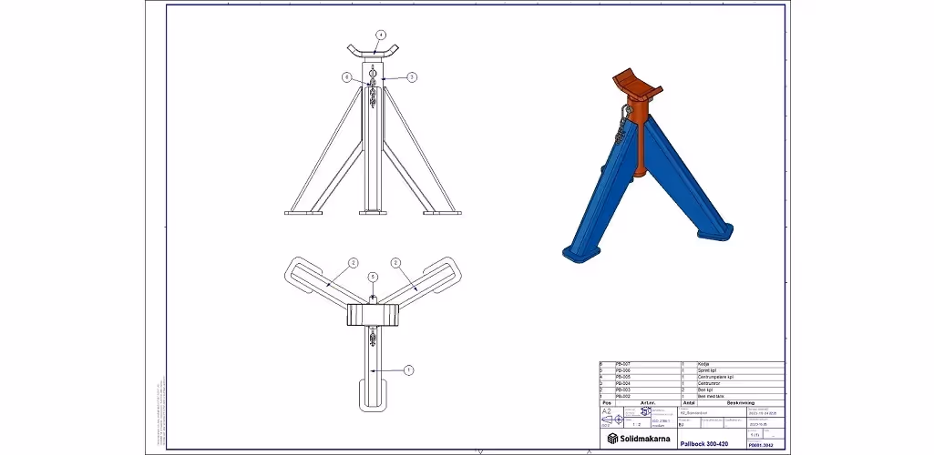

Emil Rindell

Jonas Bryntesson

Henrik Andersson
2024-03-21
Emil Rindell
Jonas Bryntesson
Henrik Andersson
2024-03-21
In the manufacturing industry and in other areas as well, you want to clearly describe how you want things to look as a finished product. Often, a preliminary sketch is made on paper or digitally what it should look like.
Many people have probably experienced that a paper base is not always the easiest to follow ("napkin drawing" or "Auto drafting" as many people jokingly call it) and there is often a greater or lesser amount of work to transform it into something you can use as a base.

Today, some form of 3D CAD system often comes into play here, and the less time you need to spend on producing a representative 3D model, the more you can spend on production documentation and manufacturing (but even there, of course, you want to reduce lead times).
Today, a lot of things can be manufactured directly from a CAD-based 3D model via e.g. a numerically controlled manufacturing machine or a 3D printer and there are several industries where a paper-based drawing base is no longer produced in the classic way and even this can follow ISO standards and cover all the legal documents needed. There are many answers to this question which is still widely discussed in the manufacturing industry in different ways.
There are areas and production methods where some form of dimensioned drawing is still needed and we still get some questions about what to consider when you want to make drawings from your 3D models and at the same time follow standards so that the recipient gets what they expect. You may not have the technical background to know what a drawing should look like or what standards and rules you should follow.
This post is primarily aimed at those who use IRONCAD to design their products and want to make production drawings for them. It is a form of self-study that you can follow entirely on your own and will help you to understand what you might need to consider when making a drawing and what can be expected to be included in it, so that the result is as planned.
In IRONCAD you will find metric drawing formats that follow the ISO standard, from A0 down to A4. The A formats are based on the basic A0 format, which is approximately 1m2 and follows the SS-ISO 216 standard.
The image below shows the size of these formats in relation to each other.
A drawing is not only a descriptive document that tells the manufacturer what a part will look like in its finished state. It is also a document that tells what is described in the drawing. When it was drawn. Who made it and who approved it. With the right information on the drawing, it also becomes a legal document.
In addition, there should be an ownership and copyright clause on the drawing.
For example, when you open a drawing template in IRONCAD , the A4 template looks like this.
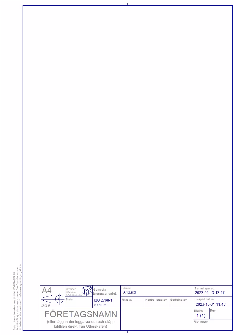
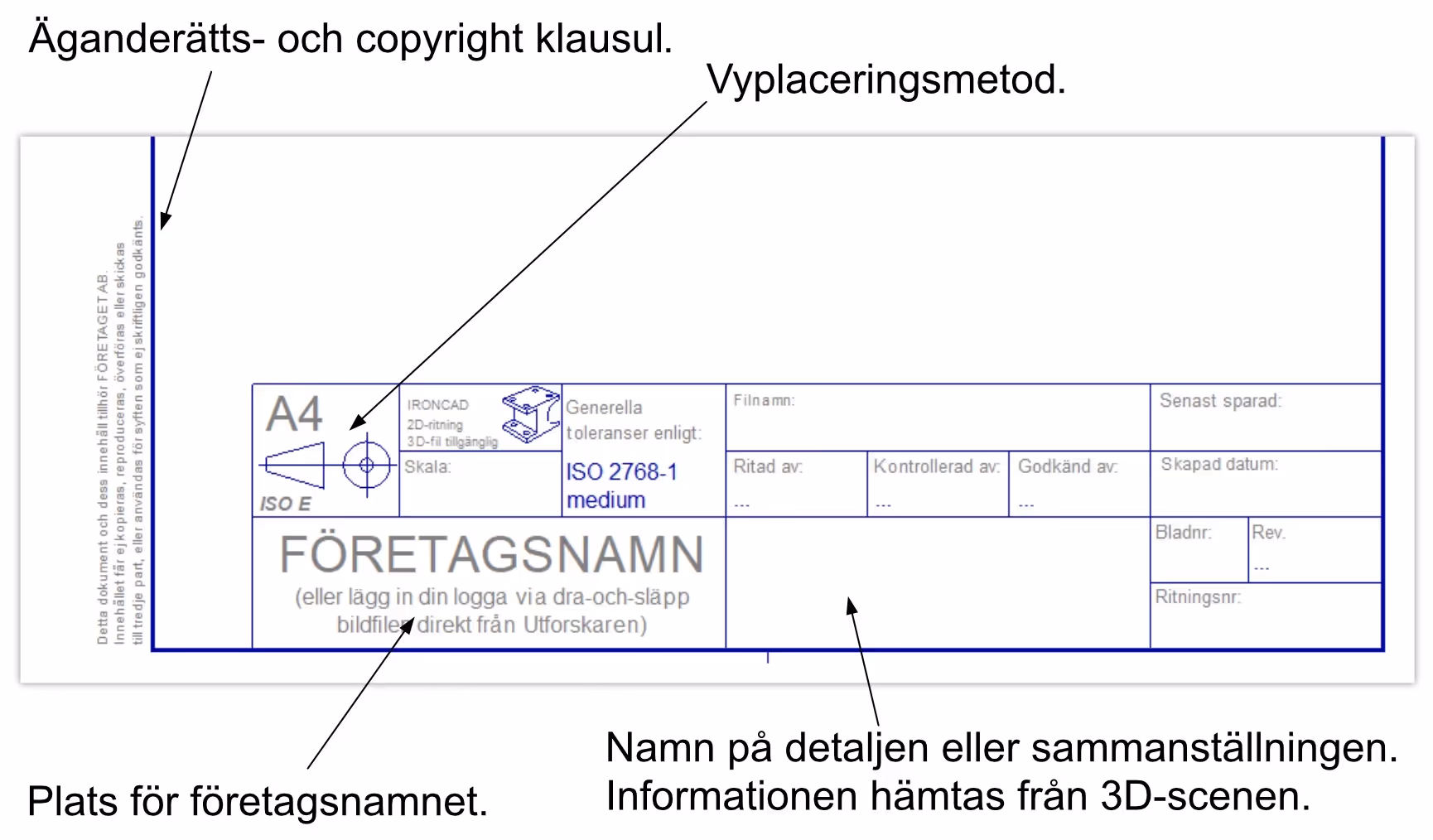
We take a closer look at the main field, which is usually placed on the right-hand side of the bottom of the drawing, and the ownership and copyright clause, which is placed on the left-hand side.
The drawing header should contain all the necessary information required such as the view placement method used, the part or assembly being depicted (a unique drawing and/or part number, designation, revision, material, weight, color and other part-unique characteristics), the scale of the drawing views, who created the drawing (Drawn by), at what time(Created date and Last saved date) and space for the company name and contact details or logo. In addition, you can enter the sheet number if more sheets belong to the set of drawings.
Don't forget to make sure that your company name is included in the text of the ownership and copyright clause.
See video below on how you can edit the drawing header in your own drawing template in IRONCAD .
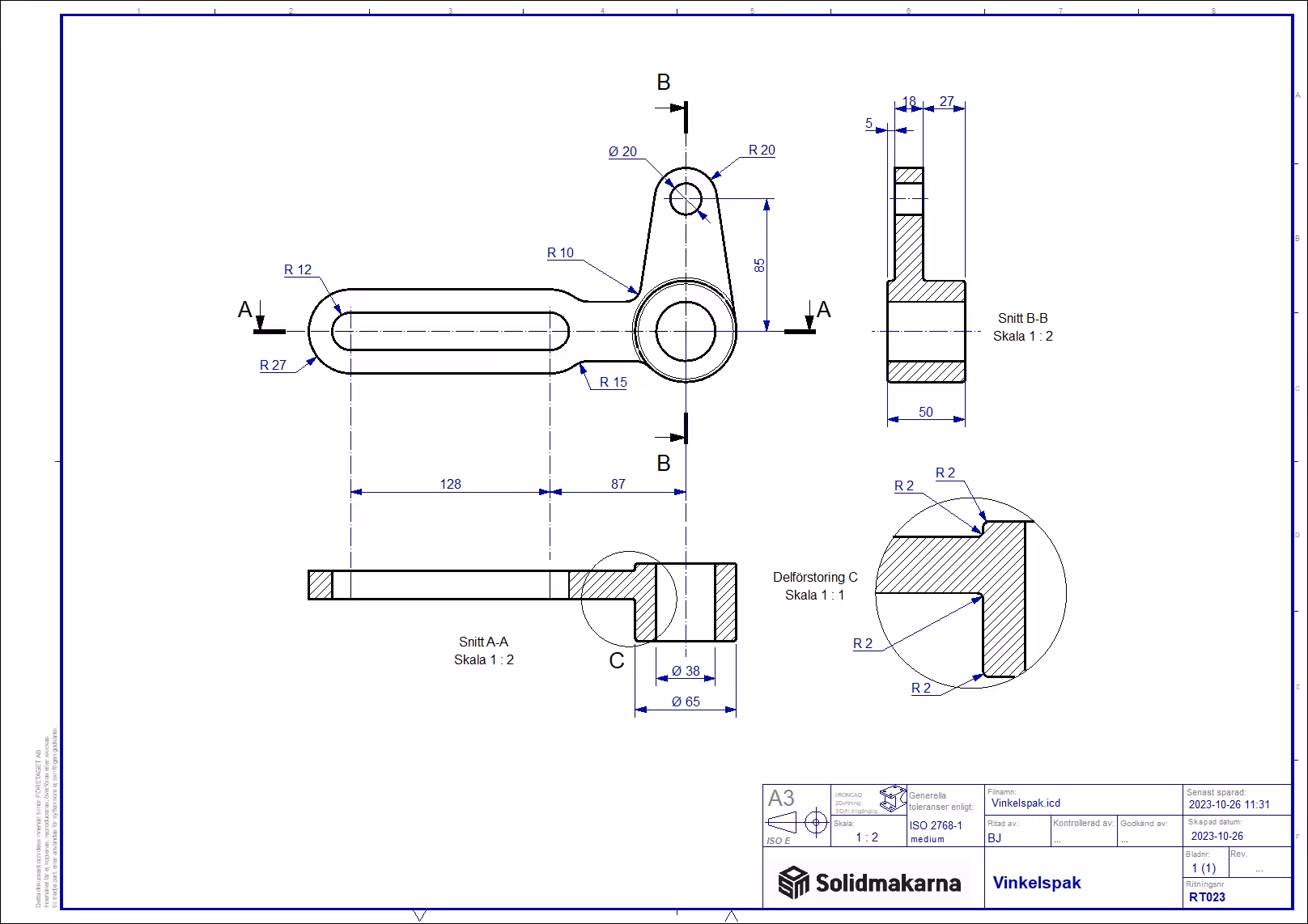
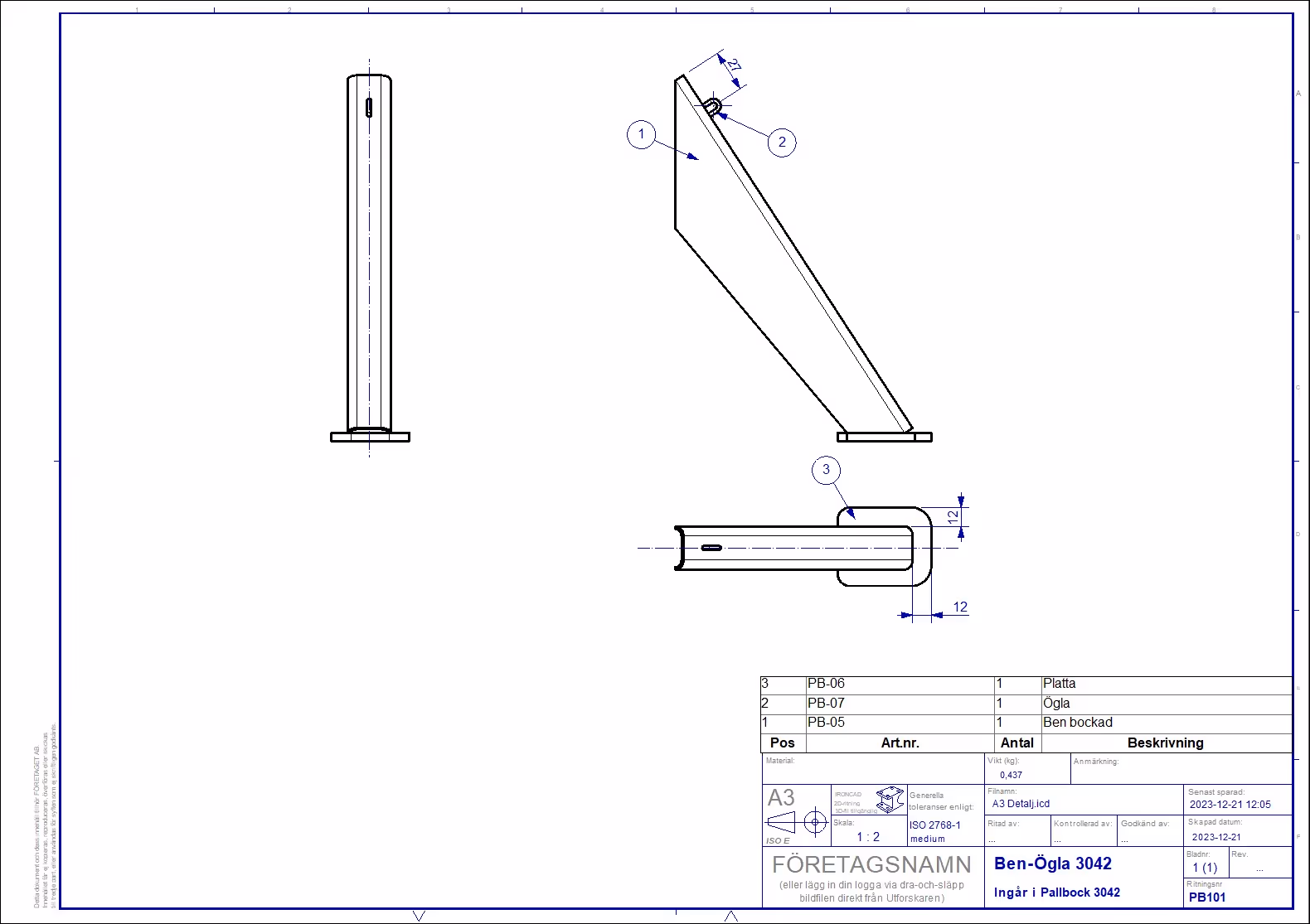
A detailed drawing in A3 format might look like this when all views are inserted and dimensions are taken.
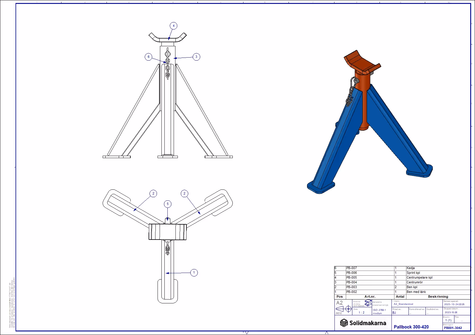
An assembly drawing shows an assembled product. In this case, the drawing contains a product with several sub-assemblies which in turn have separate drawings. The drawing contains a parts list that tells you the names of the constituent parts and the part number, which is also the drawing number, of the part.
Watch the video on how to transfer information from the 3D scene.
According to SS-ISO 128-24, there are standardizing line widths. They are referred to as narrow line, wide line and extra wide line. On machine drawings, two widths are normally used, wide line and narrow line.
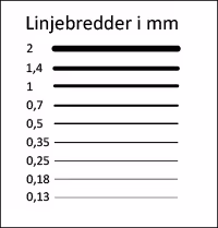
The standardized line widths in mm are shown in the box. The image is not to scale but shows the width of the lines in relation to each other.
The line widths normally used on machine drawings are 0.5 as a wide line and 0.25 as a narrow line.
On larger drawings such as A0 and A1, you can use 0.7 as a wide line and 0.35 as a narrow line. The reason for this is that it is easier to see and understand the drawing, and when reducing the size, e.g. from A1 to A3, the lines are not too thin to be read.
Types of lines
In addition to different line widths, there are also different line types as shown in the "Line types" image below.

These eight line types are standard on machine drawings;
Line1 is mainly used as a contour line.
Line2 is used for dimension lines, section markings and break lines.
Line3 is used for blurred edges and contours.
Line4 is rarely used, but mainly to mark a surface where surface treatment is allowed (e.g. heat treatment) and is drawn outside, parallel to, the contour line.
Line5 is used as a centerline and pitch circle for holes.
Line6 is used to mark the area to be coated.
Line7.
Line8 is used as a cut line.
The SS-ISO 128-20 standard precisely defines the appearance of the lines, e.g. line length and distance between points and lines.
When making a part, you want a drawing that describes what it looks like. Preferably from different sides so that you get as complete a picture as possible.
As long as it is not a spherical detail, you need at least two sides or two views on a drawing. If it's a complicated part, you might need six views and maybe even some sectional views.
The views are placed according to a standard called SS-ISO 5456-2.
Watch this video to compare the difference between how Method E and Method A work when looking at a detail:
We will use method E.
How does method E work?
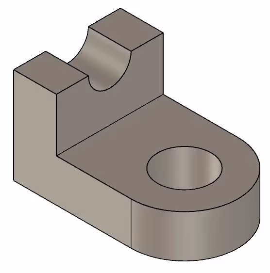
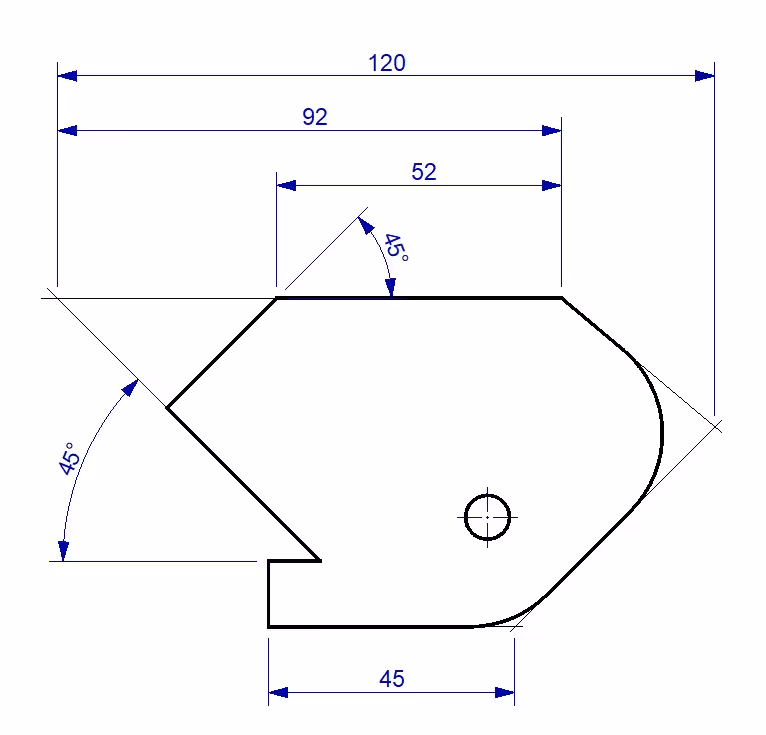
If we want to transfer this angle bracket to a drawing, we first need to find out which side will be the front or Front View on the drawing. You try to choose the side that tells the most about the part as Front View. In this case it is chosen to see the part in the following way.
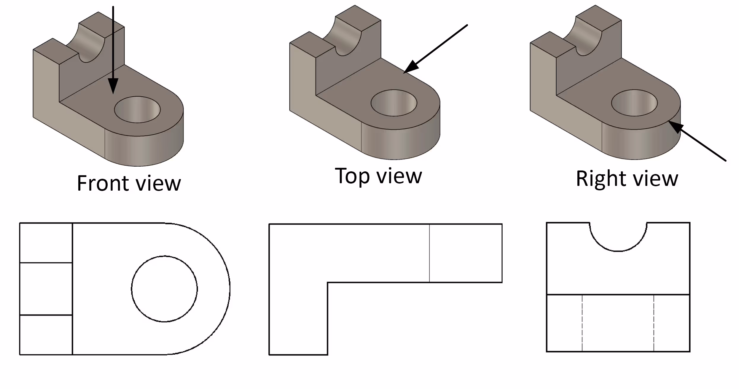
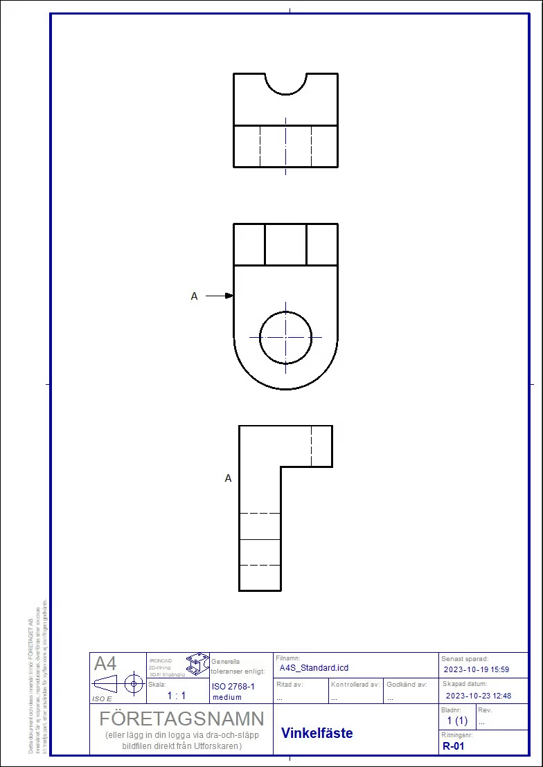
When the views are transferred to the drawing, it will look like this.

To practice making a drawing with drawing views in IRONCAD you can follow the practice video below and also download 3D models Part View placement in IRONCAD * .ics format.
You can of course also use IRONCAD to create the 3D model used in the exercise by following the video below.
The piling method
Then there is the arrow method which can be a complement to method E. when there is no space to place a view according to the view placement method indicated on the drawing. An extra view is then placed and a reference arrow is used towards the side you are looking at. The additional view is placed in an arbitrary location on the drawing, but in a location that makes it easy to read the drawing. As in the example below.
To use the arrow method you need to know how to move views on the drawing in IRONCAD.
To learn how you can use the arrow method , watch the video below.
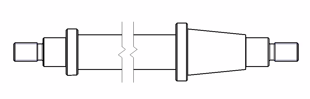
Broken view
Details that are too long to fit entirely on the paper can be drawn as a broken view, if the view is sufficient to describe the detail. The axis used in the example is broken (hidden) along the cylindrical surface where there are no additional details that need to be described in the drawing.
Watch a video on how to use a broken view - Download the 3D model Spider in IRONCAD * .ics format.
When a regular view is both difficult to read and to measure as in the picture below, a sectional view can be the solution.
Since the standard does not measure against obscured edges and contours, a sectional view is needed to make edges and contours visible as in the picture below.
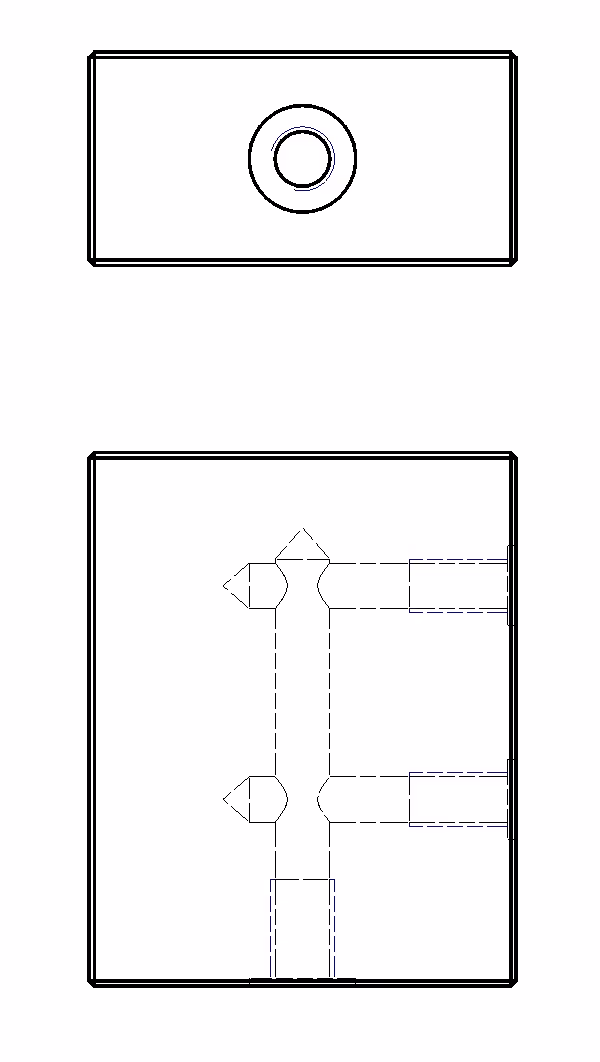
In some situations you may need to make a cut in different planes. This could be where holes or recesses are not parallel. As the picture below shows.

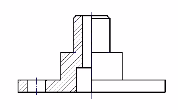
When describing and dimensioning rotationally symmetrical parts on a drawing, it is advantageous to use a half section. The picture below shows the left half of the part with a section.
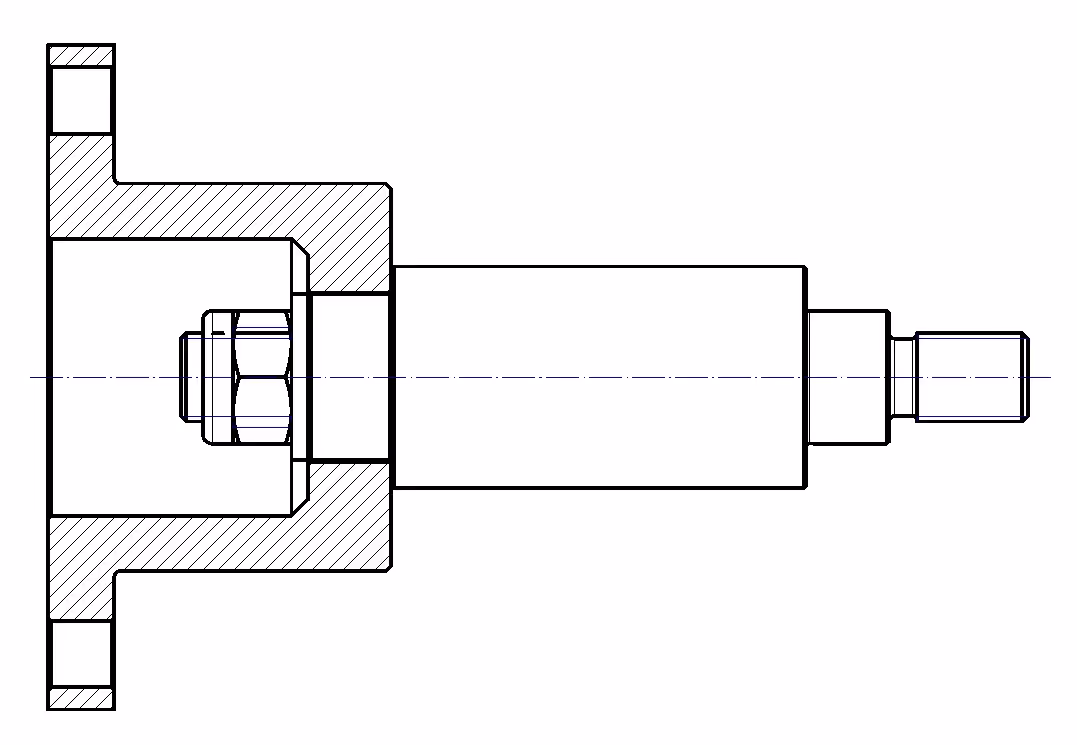
To make the cut clearer, you can choose not to cut certain details, such as axles and standard components like screws, nuts and washers.
To see how to make different cuts in IRONCAD, watch the four videos below.
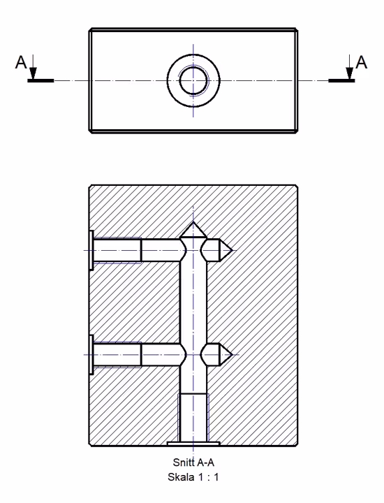
A video on how to place a Plant section - Download the 3D model Valve block in IRONCAD * .ics format.
A video on how to place a Section in different planes - Download the 3D model Block with holes in IRONCAD * .ics format.
A video showing how to create a Partial Section - Download the 3D model Connection in IRONCAD * .ics format.
A video showing how to put a Section in an assembly - Download the 3D model XXXXX in IRONCAD *.ics format.
When creating a drawing in IRONCAD , you can choose the scale already when selecting views by using the Create Standard Views command.
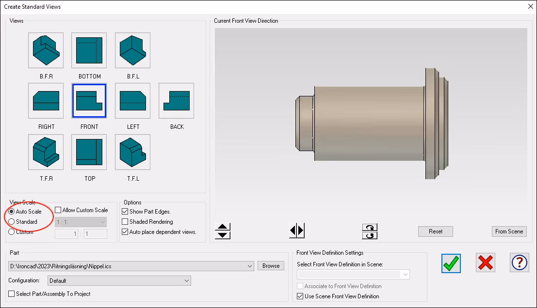
Here you can let the program automatically choose the scale based on what fits on the paper or you can specify the exact scale you want. Depending on the size and richness of the detail, you must also consider choosing the appropriate size on the drawing form itself, which can also be changed afterwards (link).
It is also possible to change the scale of one or more views afterwards. Remember to enter the scale in the drawing header, if it is not already set to load it automatically.
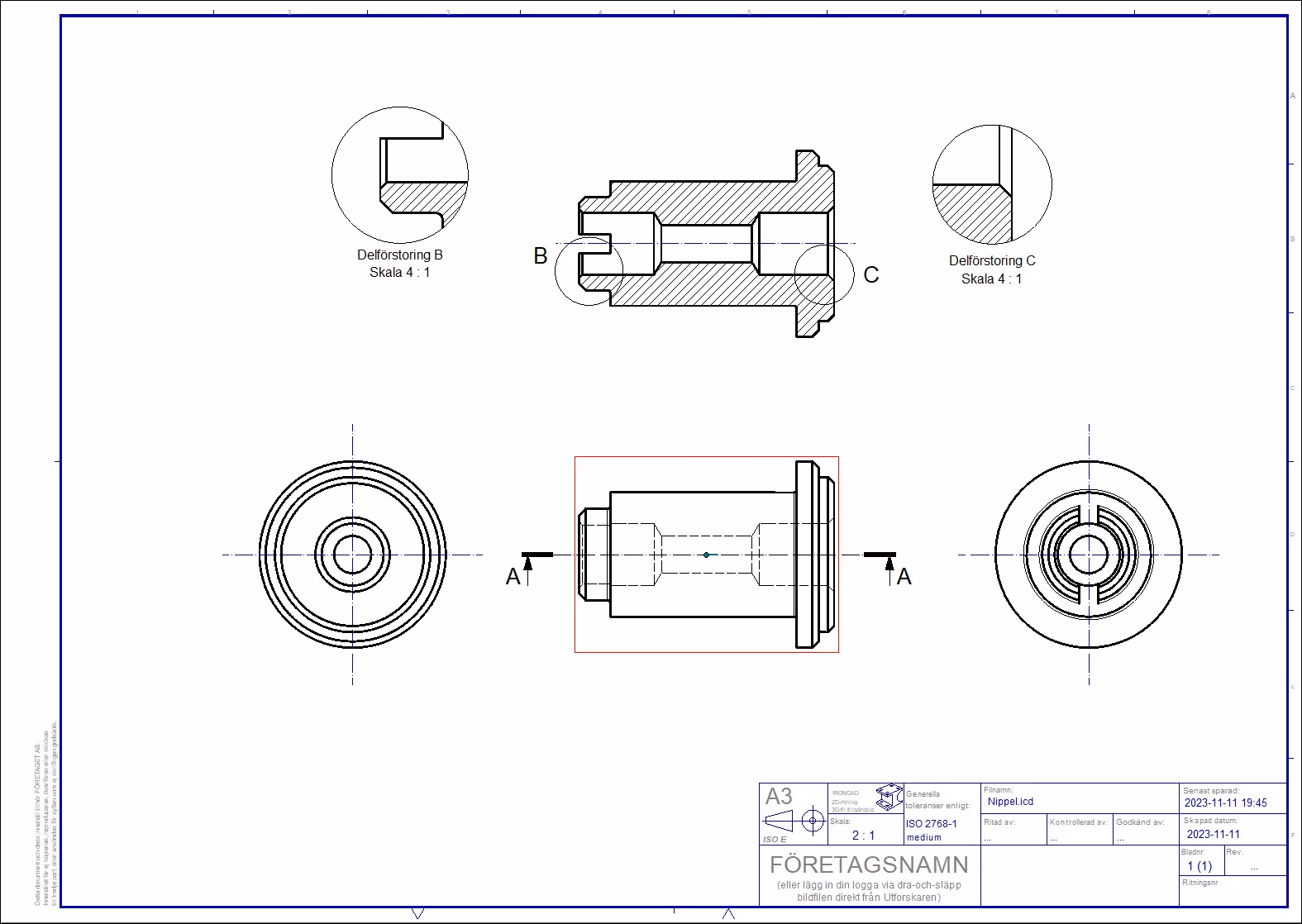
Partial magnification
For small details, you may need to use partial enlargements to show what the detail looks like but also to be able to measure.
A video showing how to determine scale - Download the 3D model Nipple in IRONCAD * .ics format.
Dimensioning of drawings is important so that the person manufacturing the part can achieve the right result. It is also important that the dimensions are consistent. Therefore, there is a standard called SS-ISO 129-1 that applies to all types of drawings in different industries.
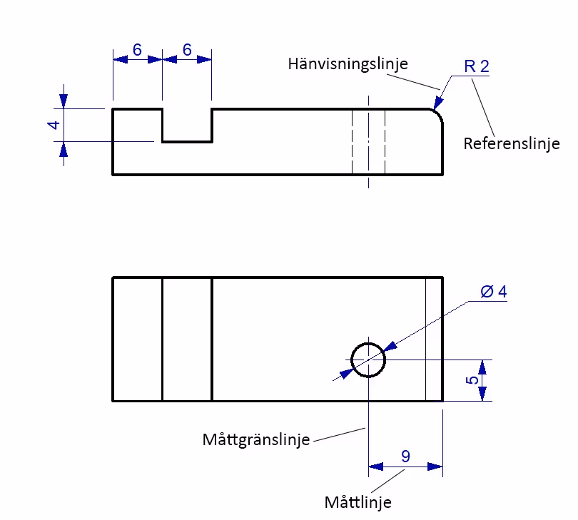
A measure is indicated by using measure boundary lines, measure line with arrows. In some situations the arrows can be replaced if the space does not allow arrows.
Dimension lines, dimension limit lines and reference lines are drawn with a solid narrow line. This means that if the contour lines have a line width of 0.5mm, the dimension lines have a line width of 0.25mm.
For larger drawings such as A1 and A0, contour lines can be drawn with a line width of 0.7mm and dimension lines with 0.35mm.
For the arrowheads of the dimension line, the angle should be either 30 degrees or 90 degrees. The arrowhead can be drawn in three ways: open, closed or filled. The 90 degree arrowhead is always drawn open.
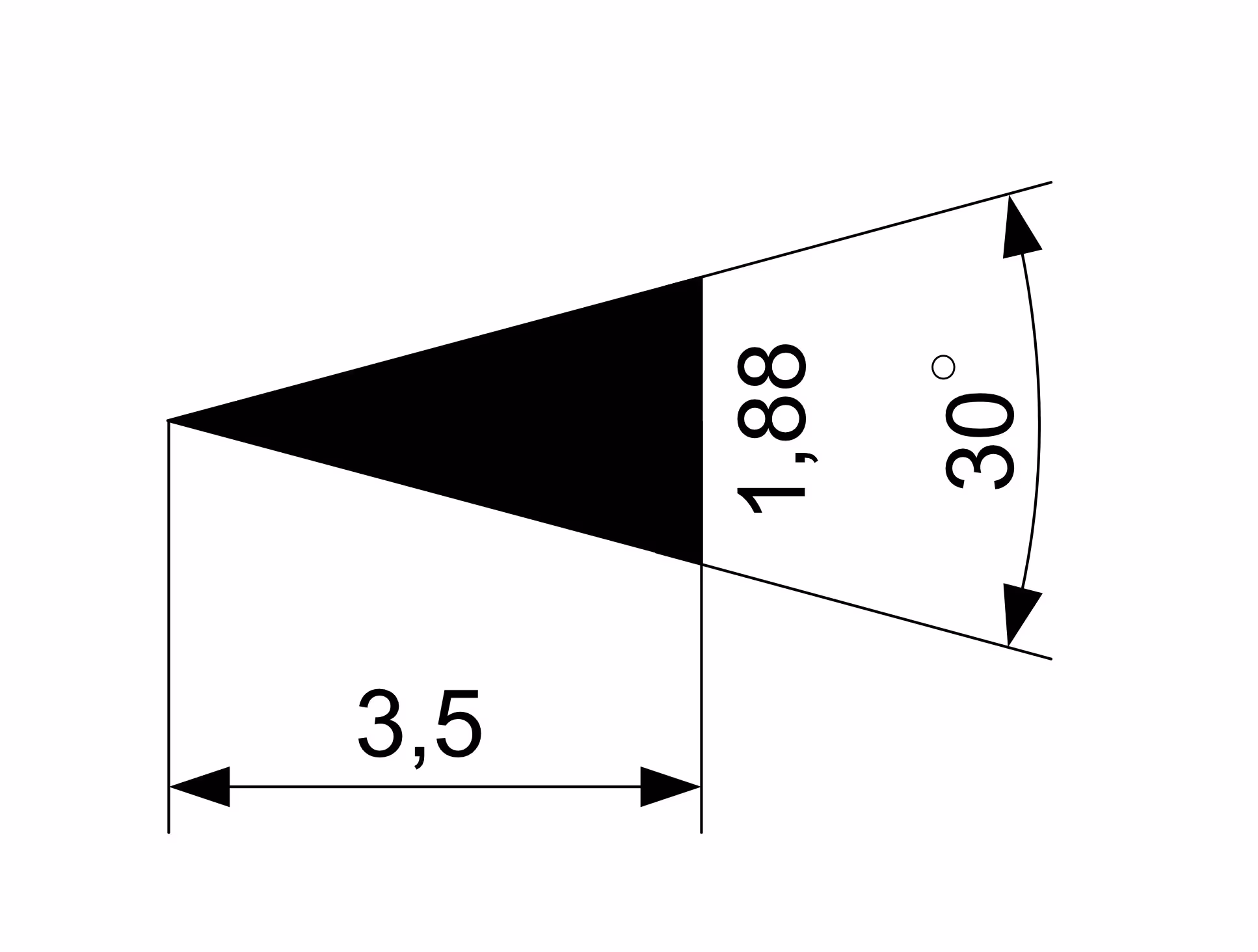
The size of the arrowhead is determined by the text size. If the drawing is drawn with line widths of 0.5mm and 0.25mm, the text height can be 3.5mm, the arrowhead should be 3.5mm long.
In the drawing templates in IRONCAD the text height is set to 12 points and the font Arial is used by default. The arrowheads are set by default to 3.5mm long with a 30 degree angle as shown above.
The dimensions should describe the size of the part. It is also important that the dimensions are placed so that they are easy to read. For example, you should try to avoid placing the dimensions so that the dimension line is broken by a dimension limit line as in the case below.
A video showing how to - Download the 3D model Nipple in IRONCAD *.ics format.
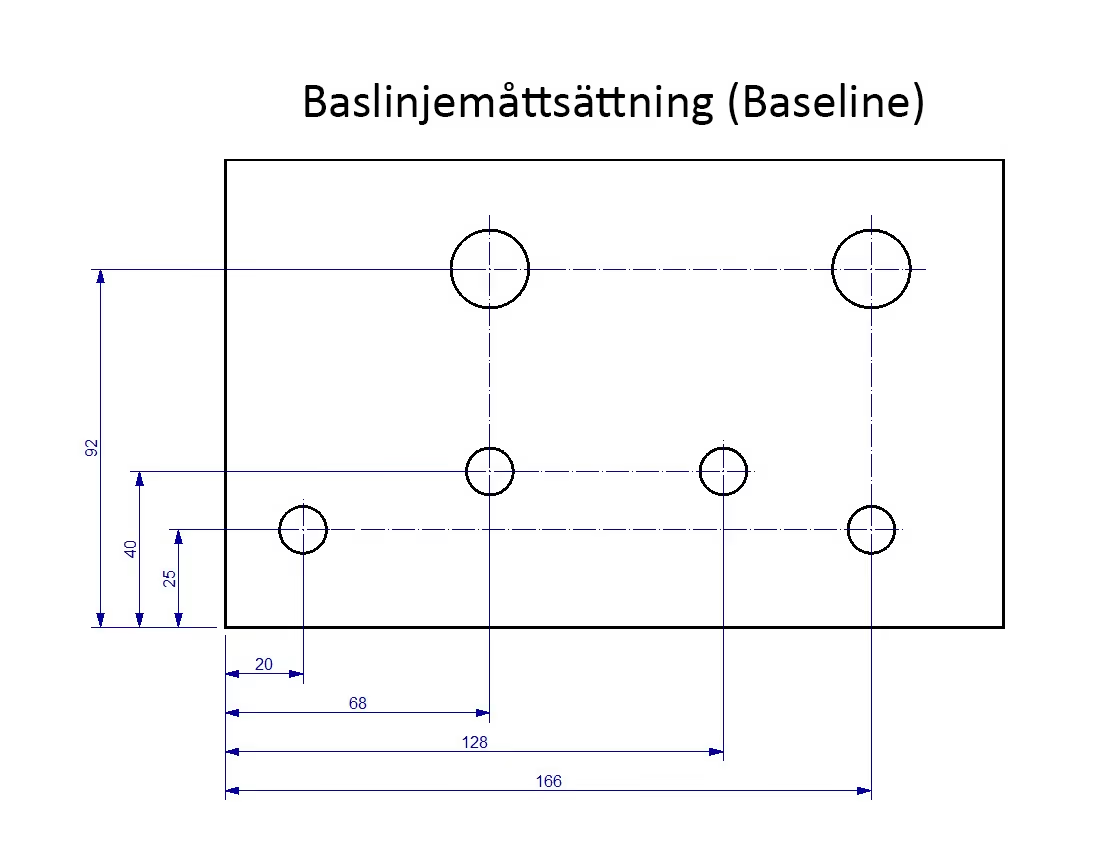
Baseline and chain measurement
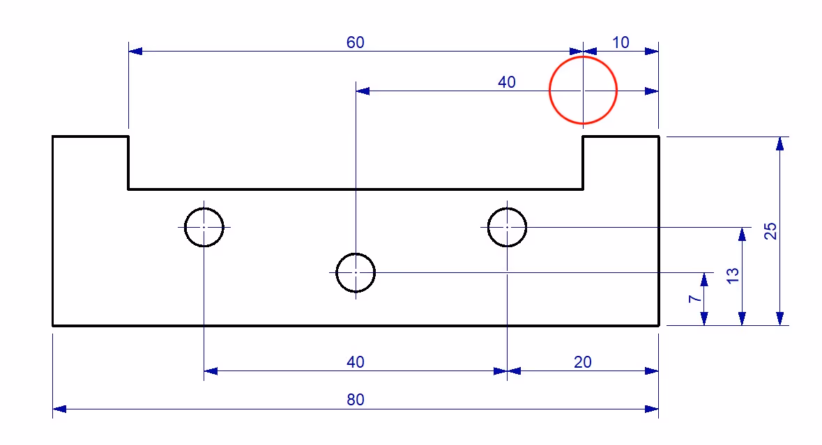
A detail can be measured in different ways as shown in the pictures below. When space is available, baseline measurement can be used. All measurements then start from a baseline, which is the left edge of the image below.
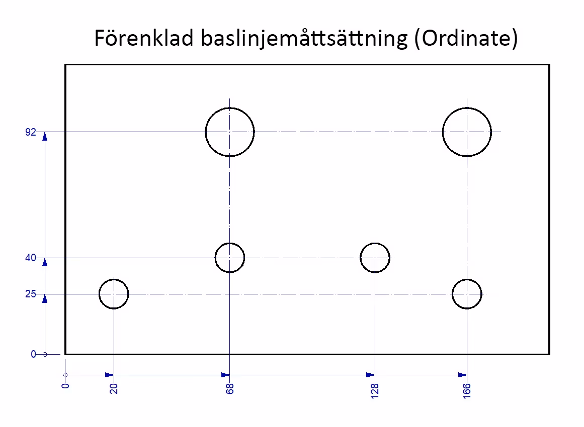
However, it is also possible to use a simplified baseline measurement or chain measurement to save space. In this case, the baseline is marked with a small circle (measure '0') and the measurement task should be placed close to the corresponding measurement boundary line as in the picture below.
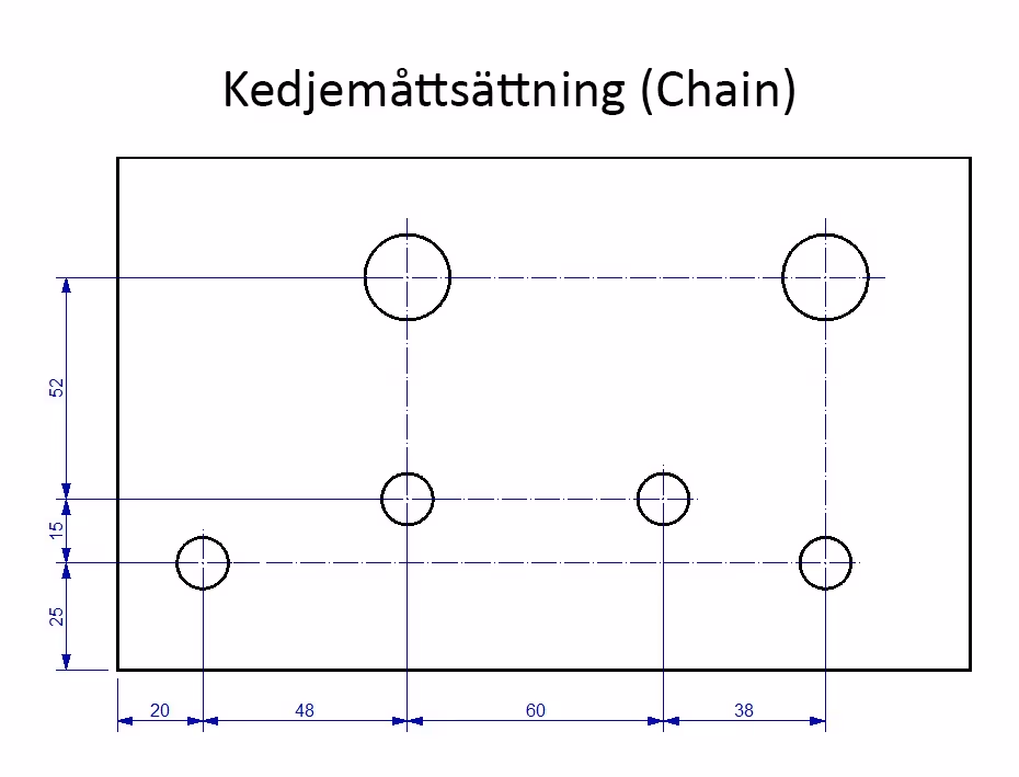
In chain dimensioning, the dimensions are laid out in a "running chain" to the points. In the picture below, it is the distance between the holes that is important from a functional point of view.
NOTE! Keep in mind that any tolerances affect which measurements are important for the function and that this may affect which of these three methods is most appropriate to use.
A video showing baseline and chain dimensioning - Download the 3D model Plate with holes in IRONCAD * .ics format.
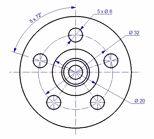
Circular dimensioning
When measuring a circular hole pattern, a centerline is inserted through the holes to get the diameter measurement of the hole pattern as in the picture below.
A video on circular dimensioning - Download the 3D model Connection in IRONCAD * .ics format.
Construction lines to help
In some cases you may need to extend a contour line with a construction line just to be able to dimension the part before machining. The construction line is drawn with a solid fine line.
NOTE! The construction lines are drawn slightly past the point of intersection so as not to be confused with the contour line.
Watch video on adding construction lines in the drawing - Download the 3D model Stop in IRONCAD * .ics format.
Measuring the broken view
If the part contains holes, like the list in the picture below, you can make a broken view and measure the pitch distance and indicate how many there are and the total distance between the first and last hole.
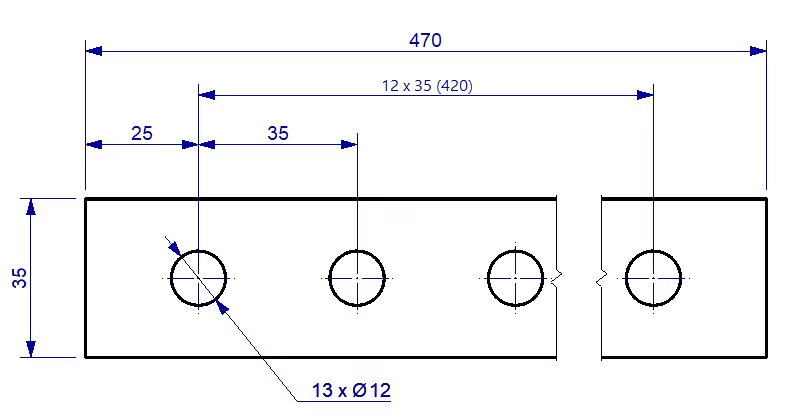
See video on how to dimension a broken view - Download the 3D model List in IRONCAD * .ics format.
A drawing includes a general tolerance indication, which is usually given in the drawing header. However, for some dimensions you may need to be more specific in terms of tolerances.
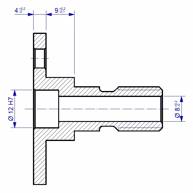
By accessing the properties of the dimension, Linear Dimension Properties, you will find the tab and the settings Tolerancing. There you can add the tolerances you want the dimension to have.
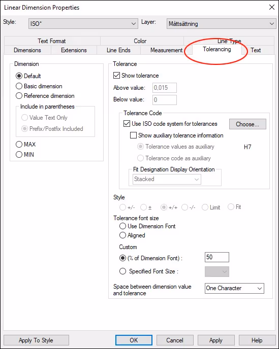
See video showing how to set a tolerance to a dimension - Download the 3D model Connection in IRONCAD * .ics format.
In IRONCAD you can find surface texture symbols through the Surface Texture Symbol command under the Annotation tab.
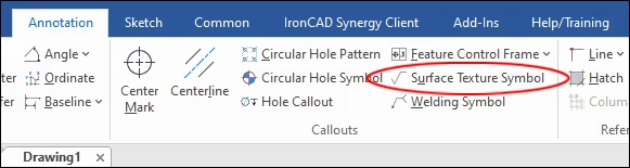
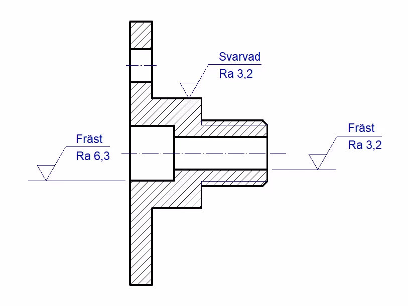
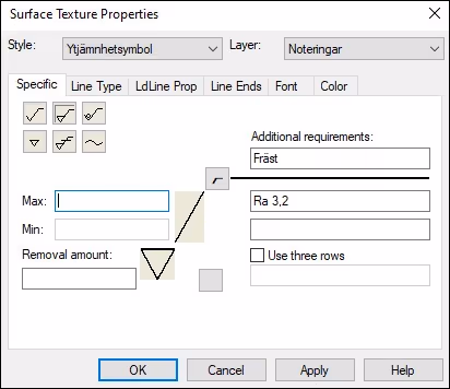
In the surface roughness symbols menu you will find all the necessary settings to mark the right surface roughness for the part you are measuring.
Watch a video on how to place surface roughness symbols... Download the 3D model Connection in IRONCAD *.ics format..
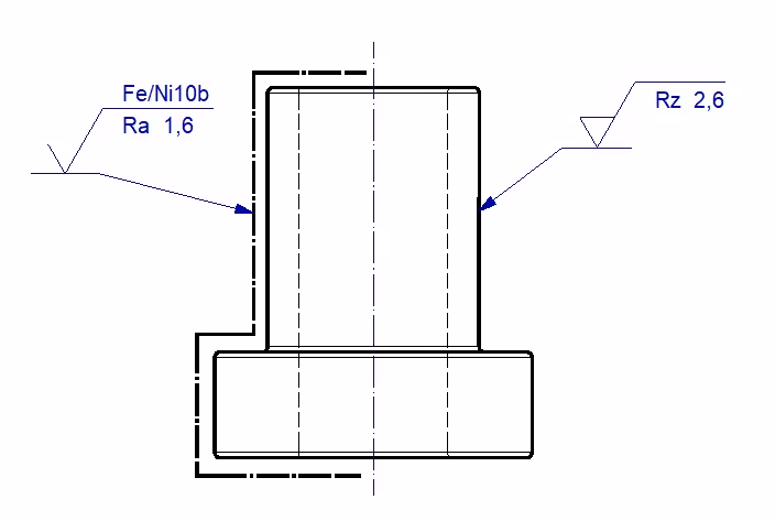
When a part is to be surface treated, for example with nickel plating, this is also indicated on the drawing. The surface structure requirements are specified both before and after surface treatment.
In addition, a broad dot-dash line is drawn to indicate the surface where the surface treatment will take place.
Watch a video on how to apply surface treatment - Download the 3D model Hylsa-nickel in IRONCAD * .ics format.
When manufacturing certain parts, it is important that, for example, shafts, holes and shaft passages are correctly positioned and that tolerances are included in the drawing. It can also be a question of flatness or parallelism between surfaces. Therefore, it is possible to add shape and position tolerances to your drawing in IRONCAD.
To do this, use the Feature Control Frame command, which can be found under the Annotation tab.
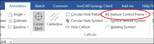
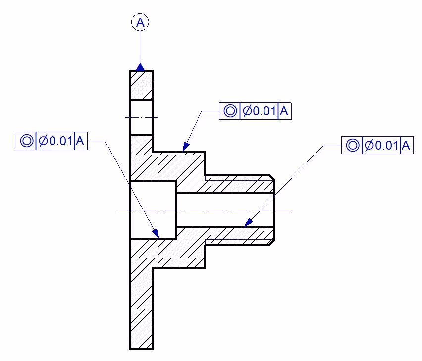
The menu contains all the necessary symbols you need to make a correct measurement of the tolerances.

See video on form and position tolerances - Download the 3D model Connection in IRONCAD * .ics format.
There are several different standards regarding welding and welding methods. There is also a standard for welding symbols to be included in a drawing. The latest standard is SS-ISO 2553, which describes how a part should be welded and with which welding method.

In IRONCAD you can find welding symbols through the Welding Symbol command under the Annotation tab.
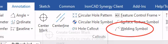

The welding symbol is drawn as an arrow with information on the design, location and method of the weld.
Watch video on welding symbols - Download the Pallbock smst file in IRONCAD * .ics format.
In IRONCAD there is no need to create separate files for assemblies and individual parts. If a product contains several different parts, all parts are made in one 3D scene. This facilitates the organization of the constituent parts of the product.
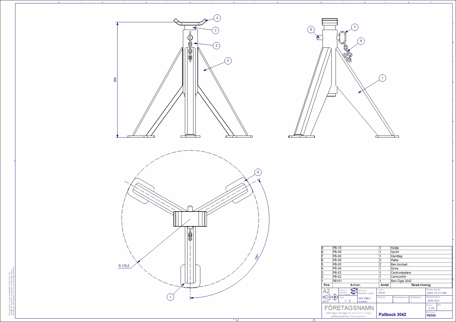
This means making assemblies and sub-assemblies in a single 3D scene. Then assembly drawings and sub-assembly drawings are made from these in the 3D scene.
Watch thevideo on how to create assembly drawings in IRONCAD - Download the file Pallbock in IRONCAD * .ics format.
If you are interested in learning everything there is to know about IRONCAD , you can take a look at our IRONCAD-basic training at IronCAD Academy, where exercises 39 to 55 are mainly about the drawing and how it is linked to the 3D models.
If you want to take a general IRONCAD basic training course at a distance or on site with us or elsewhere, you can check the planned dates on our website.
Answer: Here we publish tips, guides, news and solutions for those who work with IRONCAD and Design Data Manager (DDM). The blog covers everything from basic functions to advanced workflows, helping you to optimize your design work. You'll find examples of smart shortcuts, practical instructions, solutions to common problems, and best practices for product design, mechanical design, and product data management.
Answer: Our guides and tips are designed for both beginners and experienced CAD users. They are aimed at designers, engineers and project managers who want to work more efficiently with IRONCAD and DDM, improve the design process, reduce mistakes and save time in product development.
Answer: We regularly publish new articles when the software is updated, when new features are introduced, or when our users ask for solutions to specific problems. The blog is therefore a reliable source for keeping up to date and getting tips that make everyday CAD work easier.
Answer: Many of our instructions and tips work in multiple versions, but we clearly indicate if an article applies to a specific version. We strive to make the content useful for older versions as well, and also provide recommendations on how to adapt workflows to the version you are using.
Answer: Absolutely! If you can't find the solution in the blog, you can contact our technical support via solidmakarna.support. Our experts will help you with everything from installation and configuration to advanced features in IRONCAD and DDM, so you can solve problems quickly and efficiently.
Answer: Yes! We appreciate suggestions from our users. If you have questions, tips or want us to address a specific issue in IRONCAD or DDM , please contact us via our contact form and we will prioritize relevant topics in future posts.
Answer: The blog contains, among other things:
Practical step-by-step guides to help you use IRONCAD and DDM more effectively.
Productivity and workflow tips for faster design and construction.
Solutions to common problems encountered by users in CAD programs.
Updates and news on new features, versions and improvements.
Best practices for data management and project organization in DDM.
Answer: All tips and guides are directly applicable in daily work. For example, you can use shortcuts and smart features in IRONCAD to speed up modeling, structure files better in Design Data Manager, or follow our step-by-step solutions for specific problems that often come up in design projects.
Answer: We strive to ensure that all guides and tips are relevant to the latest versions of IRONCAD and DDM. We also clearly mark when a post applies to an older version, so you always know if the instruction is directly applicable to your system.
Answer: Yes! Many of our users share the articles with colleagues and use them as internal training materials. The blog is a great complement to formal training and helps teams learn features faster, avoid mistakes, and standardize workflows in IRONCAD and DDM.