Looks like you don't have ESC button on your device
Download IronCAD DCS
Choose one of the following options
trial versionHas a license
Looks like you don't have ESC button on your device
Choose one of the following options
trial versionHas a license

Emil Rindell

Jonas Bryntesson

Henrik Andersson
2022-08-24
Emil Rindell
Jonas Bryntesson
Henrik Andersson
2022-08-24
This guide contains a list of general shortcuts that apply in IRONCAD. These are very good to learn as it will speed up your work and make you more productive.
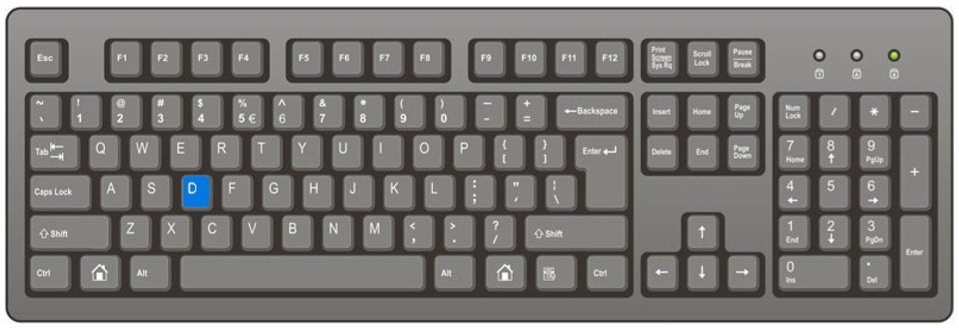
[D] - Fit the camera (Fit Scene, also on [F8] or double-click with the scroll wheel)
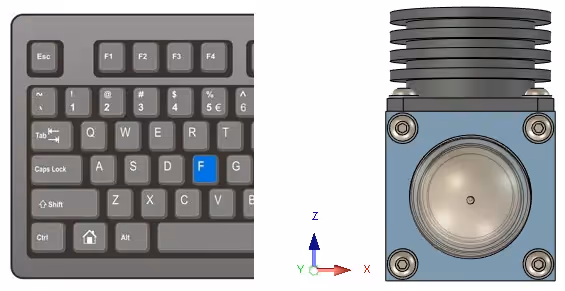
[F] - Front camera, corresponds to the so-called Front view in the 2D drawing (which is also the default mode there).
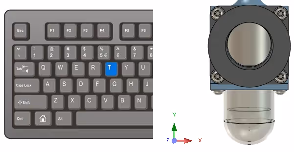
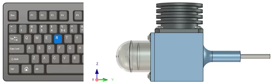
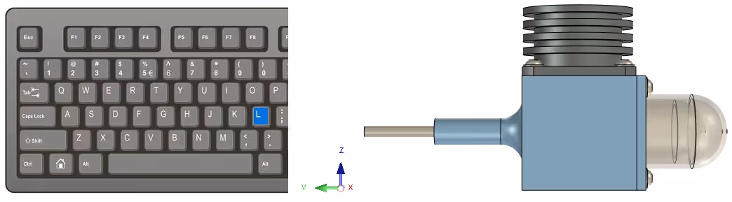
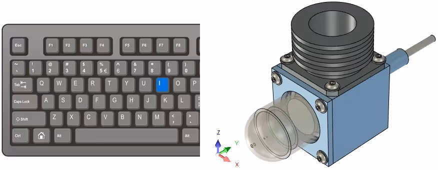
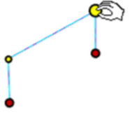
At the bottom left of each model in each image is the corresponding orientation around the XYZ coordinate system in the 3D scene.
[T] – Top view
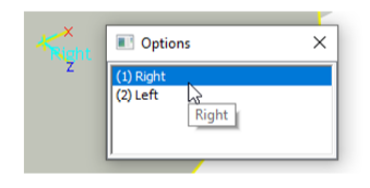
[R] – Right
[L] – Left
[B] - Back
image
[I] - Isometric camera(Top Front Right)
[W] - Look perpendicular to a surface, (Look at, also available at [F7]). Combine with the arrow keys to rotate the 3D scene in 90-degree increments.
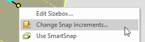
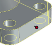
The combination [Ctrl] [Shift] and the scroll wheel (middle button) aligns the camera's center of rotation with a geometry.
Read more and watch a tips & tricks video about the camera in IRONCAD.
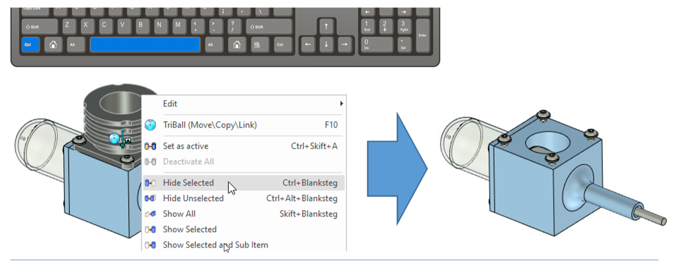
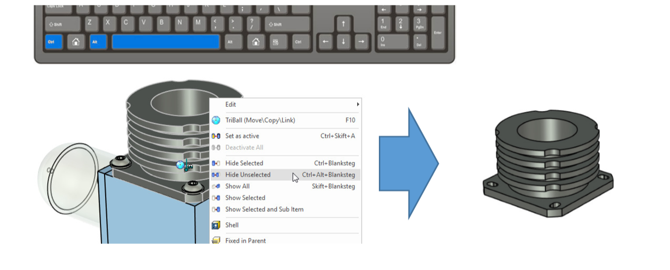
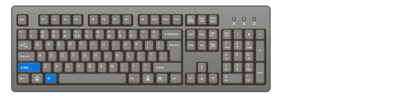
[CTRL] + [SPACEBAR]
Hide what is currently selected(Hide Selected).
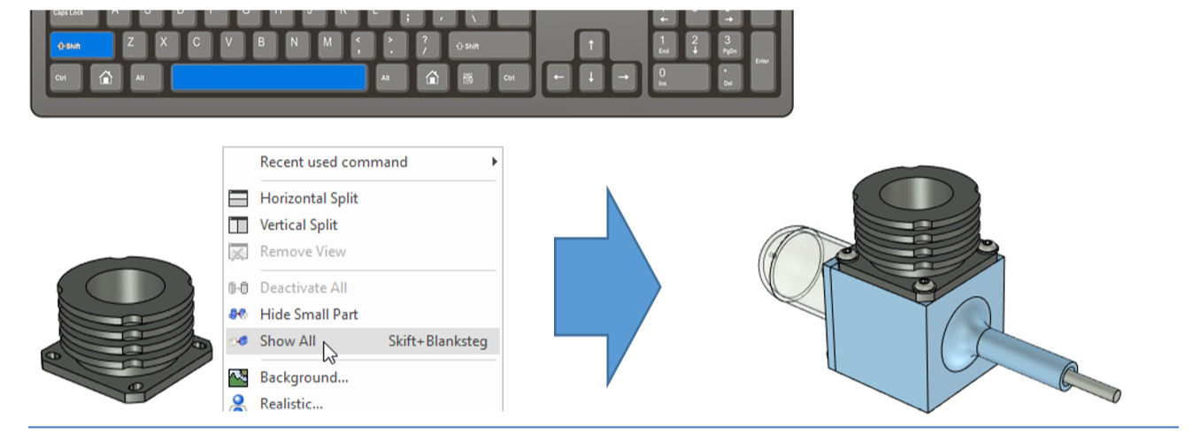
[SHIFT] + [SPACE]
Bring up all hidden items(Show All).
[CTRL] + [ALT] + [SPACE]
Hide everything except what is currently selected(Hide Unselected).
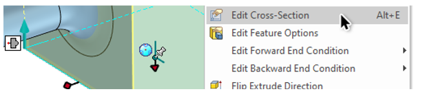
[E] - Edit a selected feature (Extrude, Blend, Shell etc).

[Alt] [E] - Edit the cross-section/sketch of the selected shape.
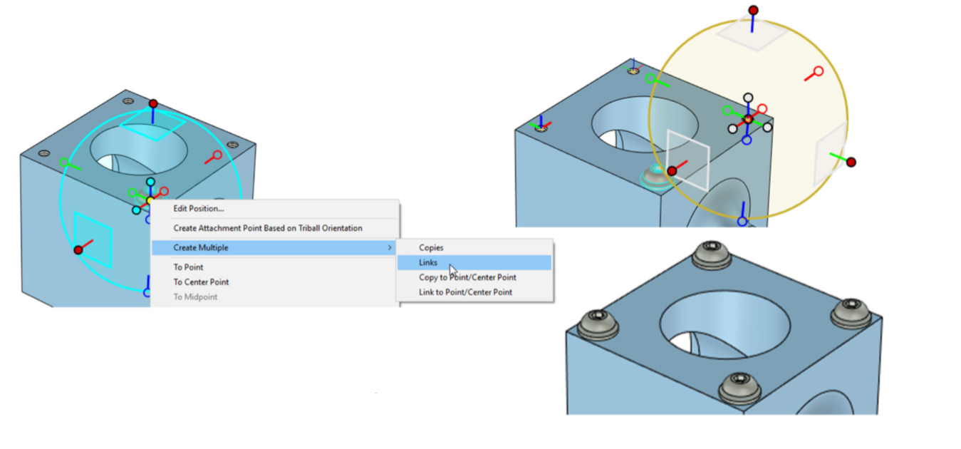
[C] or [L] when an outer handle of the TriBall is selected, creates copies (C) or linked copies (L).
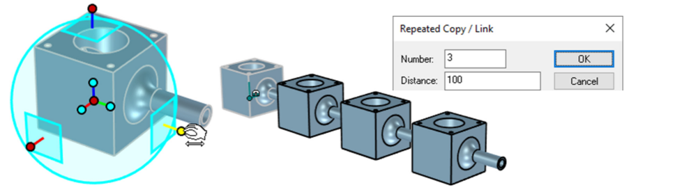
[P] - Create point with TriBall, for 3D curves or create copies/links with TriBall.
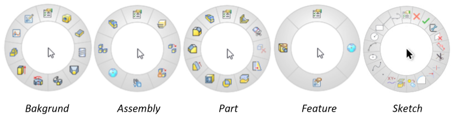
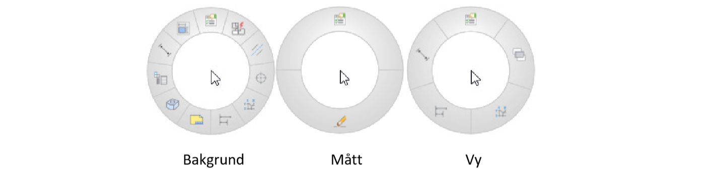
[S] - Display Quick Commands toolbar at the mouse arrow, based on what is selected.
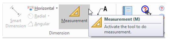
[M] - Measurement, starts the temporary measurement tool in the 3D scene. Close with [Esc].
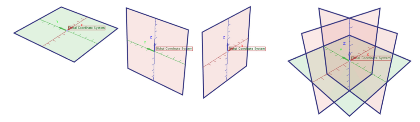
[A] - Show and hide all planes in the coordinate system.
[X] - Show and hide the YZ plane in the coordinate system.
[Y] - Show and hide the XZ plane in the coordinate system.
[Z] - Show and hide the XY plane in the coordinate system.
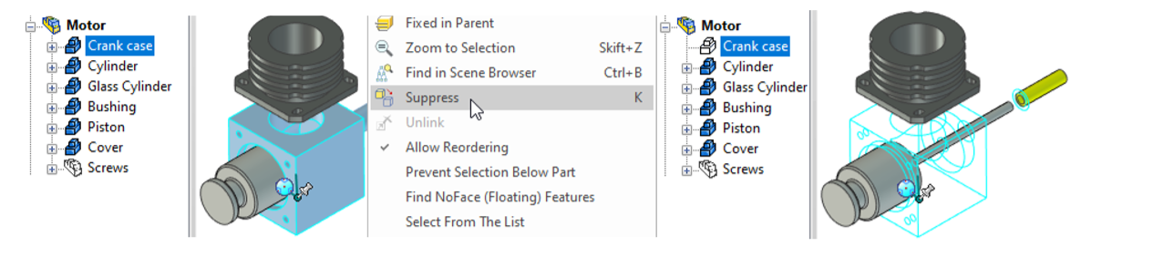
Kf_200D↩[K] - Suppress (permanently hide) one or more Assemblies, Parts or Features. Used primarily in configurations, such as a "blown up" mode, where only certain parts are to be shown. Suppressed objects are also not shown in the 2D drawing views or parts list. The icon in the history tree of the 3D scene will have a white color.
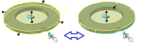
[G] - Ghost (transparent hidden "ghost model") on one or more Assemblies or parts. In this way it becomes a reference model in the 3D scene that cannot be selected or modified, only snapped to.
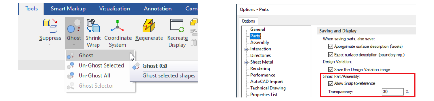
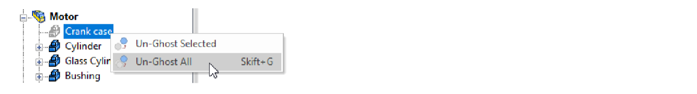
[SHIFT] + [G] - Un-Ghost All turns off the Ghost function on everything in the 3D scene.
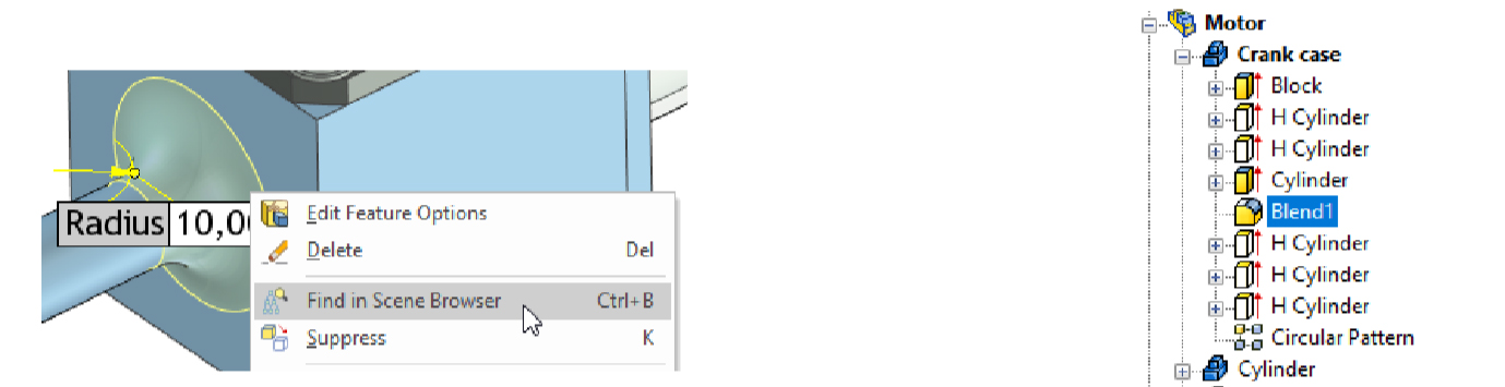
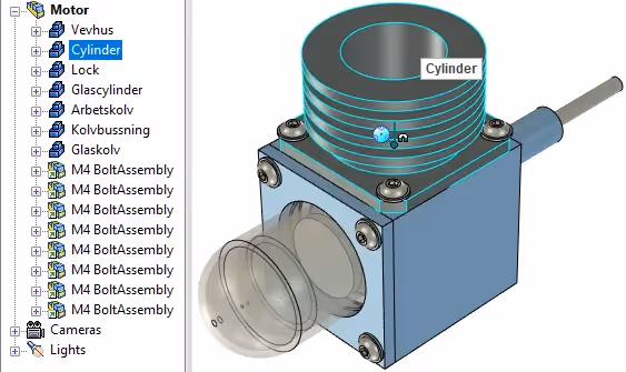
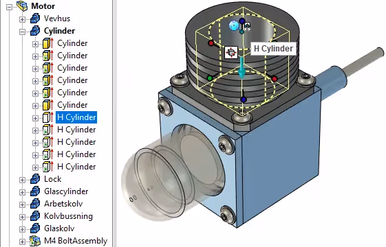
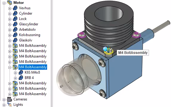
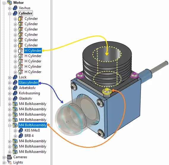
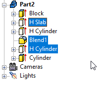
[CTRL] + [B] - Find in Scene Browser, locate and display the selected object in the story tree. Very useful when you have a long tree structure due to a complex part with many features or a large assembly with many subsets and parts in several levels.
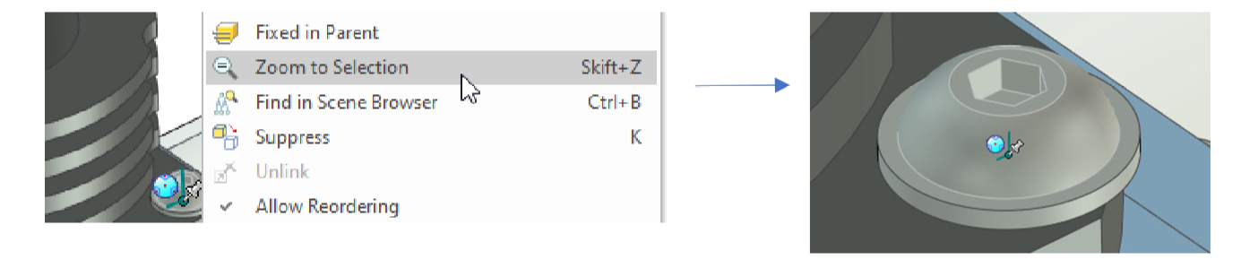
[SHIFT] + [Z] - Zoom to Selection, zooms in on the selected object on the screen. Useful e.g. after importing models that are outside the visible field in the 3D scene, but usually best accessed via the history tree.
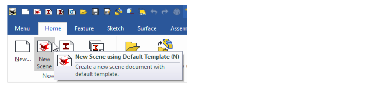
[N] - Create new empty 3D scene from the default template.
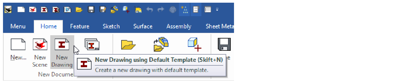
[SHIFT] + [N] - Create new empty 2D drawing from the default template.
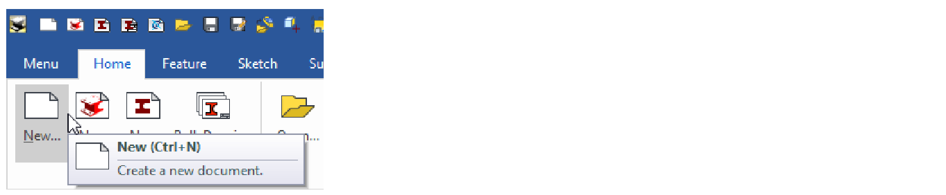
[CTRL] + [N] - Create new empty file(2D ICD, 3D ICS or 2D EXB) by selecting from a list.
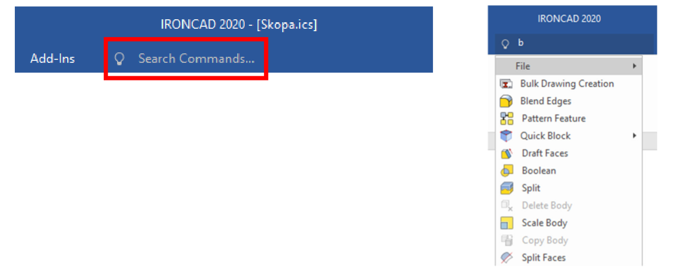
[ALT] + [Q] - Search Commands, starts the search command for tools and functions in IRONCAD. It is a Windows command that can also be run in MS Word or MS Excel.
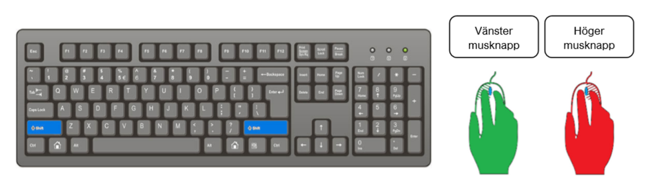
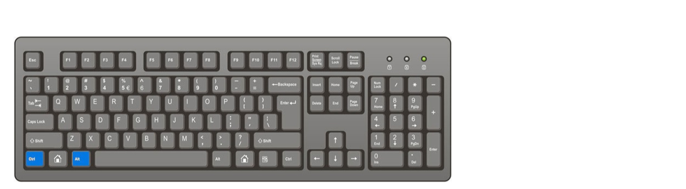
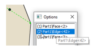
Hold down [CTRL] and left-click to directly select a part (blue borders) in the 3D scene, regardless of assemblies and other structure in the tree.
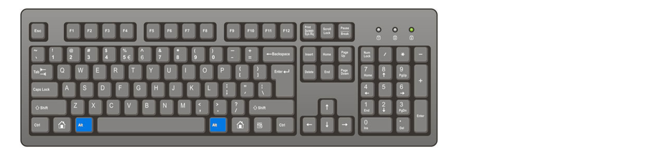
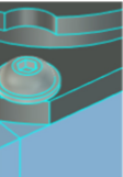
Hold down [Alt] and left-click to directly select a feature (yellow shimmering surfaces/volumes) in the 3D scene, regardless of parts, assemblies and other structure in the tree.
Hold down [Ö] and left-click to directly select the last assembly in the tree structure in the 3D scene.
Combine these above mentioned keys with [Shift] to add multiple selections one after the other in the 3D scene(Viewport) or combine with [Ctrl] to directly select multiple objects in the tree structure(Scene Browser).
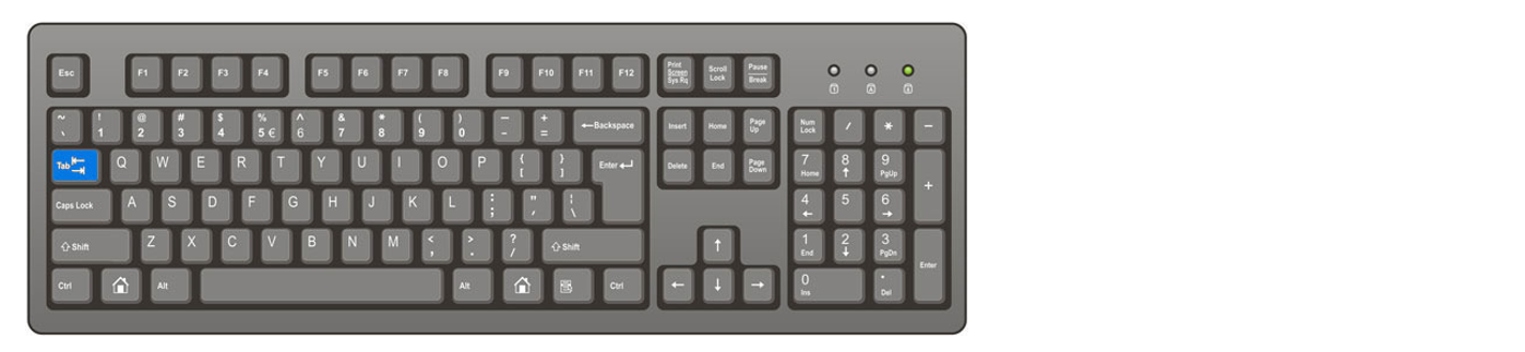
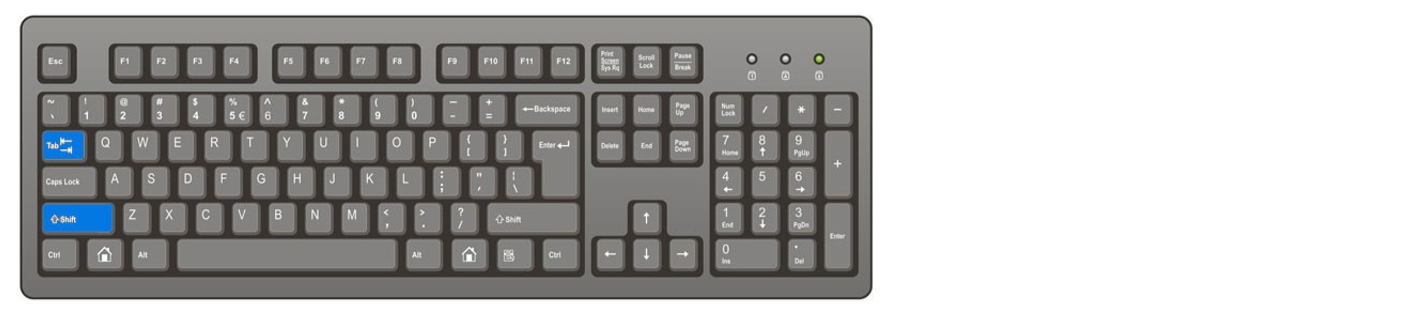
[TAB] - Toggle between Vertical, Horizontal or Parallel measurement mode for Chain, Baseline or Coordinate measurement in 2D drawing.
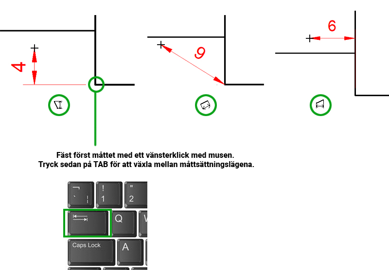
[TAB] is also used to switch the direction of a Smart Dimension that has just been placed between two points. After the second point is selected, switch between Vertical, Horizontal or Parallel.
The [TAB] key is also used to place the measurement line parallel to a non-horizontal/vertical contour line. Let the mouse cursor "rest" over the oblique contour line, when it lights up in green - press the [TAB] key.
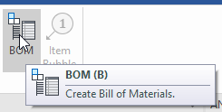
[B] - Parts list(BOM)
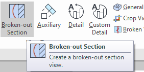
[Shift] [B] -Broken-out Section View
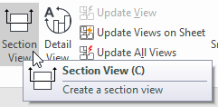
[C] - Section View (Section View)
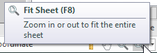
[D] / [F8] - Customize the drawing(Fit Sheet)
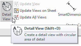
[Shift] [D] - Partial magnification view(Detail View)
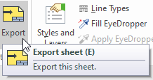
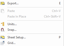
[E] - Export
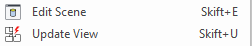
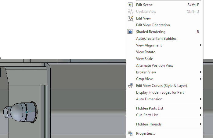
[Shift] [E] - Switch to 3D scene(Edit Scene)
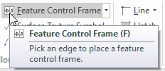
[F] - Shape and position tolerance (Feature Control Frame)
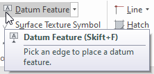
[Shift] [F] - Reference element(date Feature)
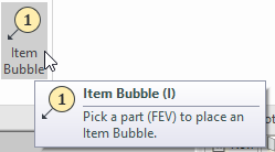
[I] - Posballong(Item Bubble)
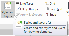
[L] - Settings(Styles and Layers)
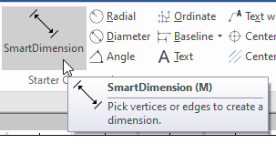
[M] - The dimensioning tool(Smart Dimension)
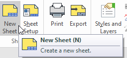
[N] - NewSheet
[P] - Sheet Setup - paper settings such as paper size and transfer of certain properties from the 3D scene.
[R] - Shaded view(Shaded Rendering)
[S] - Display the Quick Commands toolbar by the mouse arrow, based on what is selected.
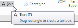
[T] - Text tool
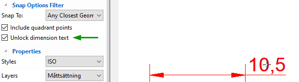
[U] - Unlock dimension text along the dimension line.
This can also be combined with the [Ctrl] key to lock the position of the dimension line and move the dimension text only.
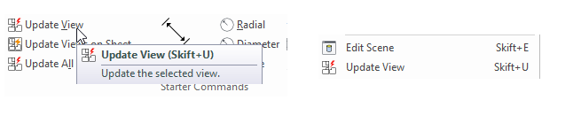
[Shift] [U] - Update SelectedView
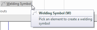
[W] - Welding Symbol
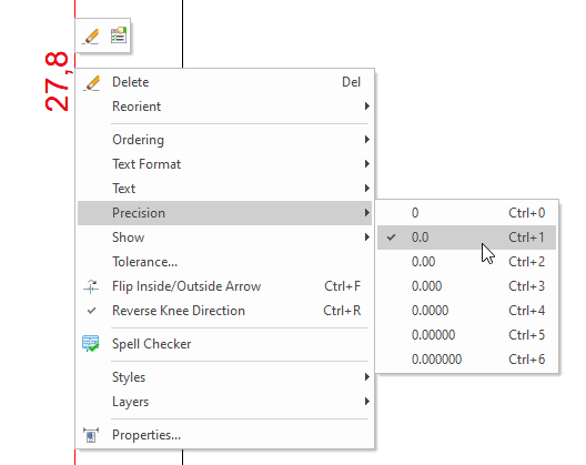
[CTRL] ["n"] - Adjust the number of decimal places on the selected measurement set, one or more at a time, where "n" corresponds to the number of decimal places.
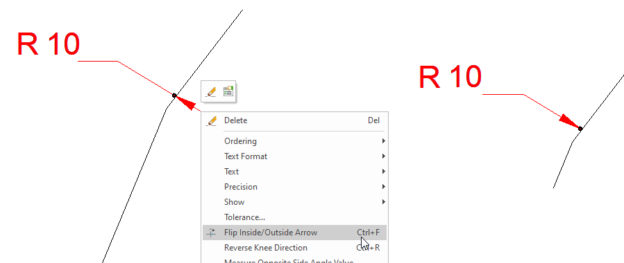
[CTRL] [F] - Change the direction of the measurement arrow. Sometimes it is too tight between the measurement boundary lines, or if the mouse pointer ends up on the inside instead of the outside when setting a radius measurement.
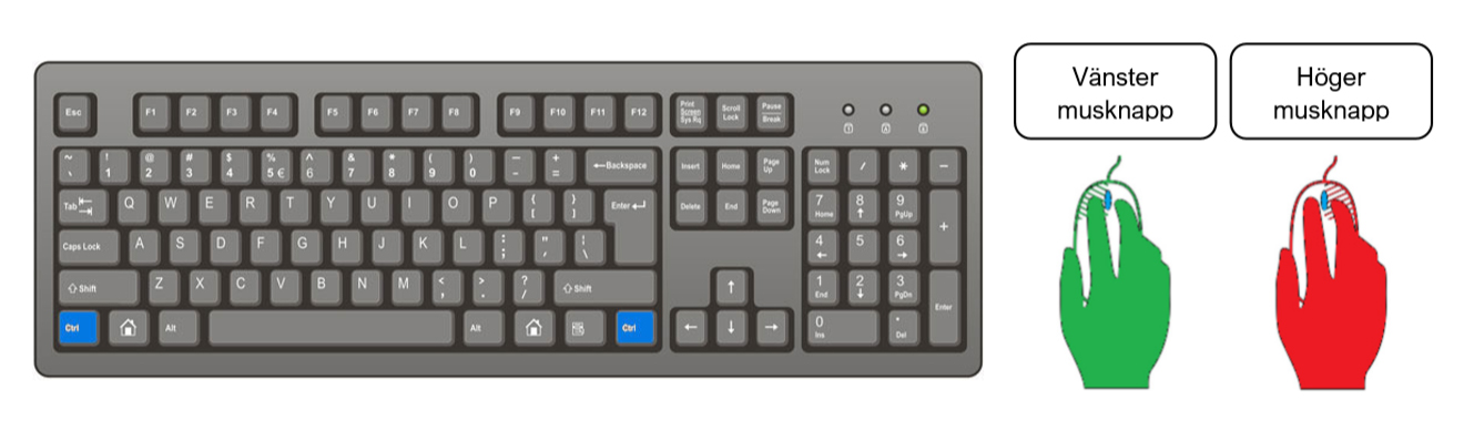
[CTRL] - hold down to:


Answer: Here we publish tips, guides, news and solutions for those who work with IRONCAD and Design Data Manager (DDM). The blog covers everything from basic functions to advanced workflows, helping you to optimize your design work. You'll find examples of smart shortcuts, practical instructions, solutions to common problems, and best practices for product design, mechanical design, and product data management.
Answer: Our guides and tips are designed for both beginners and experienced CAD users. They are aimed at designers, engineers and project managers who want to work more efficiently with IRONCAD and DDM, improve the design process, reduce mistakes and save time in product development.
Answer: We regularly publish new articles when the software is updated, when new features are introduced, or when our users ask for solutions to specific problems. The blog is therefore a reliable source for keeping up to date and getting tips that make everyday CAD work easier.
Answer: Many of our instructions and tips work in multiple versions, but we clearly indicate if an article applies to a specific version. We strive to make the content useful for older versions as well, and also provide recommendations on how to adapt workflows to the version you are using.
Answer: Absolutely! If you can't find the solution in the blog, you can contact our technical support via solidmakarna.support. Our experts will help you with everything from installation and configuration to advanced features in IRONCAD and DDM, so you can solve problems quickly and efficiently.
Answer: Yes! We appreciate suggestions from our users. If you have questions, tips or want us to address a specific issue in IRONCAD or DDM , please contact us via our contact form and we will prioritize relevant topics in future posts.
Answer: The blog contains, among other things:
Practical step-by-step guides to help you use IRONCAD and DDM more effectively.
Productivity and workflow tips for faster design and construction.
Solutions to common problems encountered by users in CAD programs.
Updates and news on new features, versions and improvements.
Best practices for data management and project organization in DDM.
Answer: All tips and guides are directly applicable in daily work. For example, you can use shortcuts and smart features in IRONCAD to speed up modeling, structure files better in Design Data Manager, or follow our step-by-step solutions for specific problems that often come up in design projects.
Answer: We strive to ensure that all guides and tips are relevant to the latest versions of IRONCAD and DDM. We also clearly mark when a post applies to an older version, so you always know if the instruction is directly applicable to your system.
Answer: Yes! Many of our users share the articles with colleagues and use them as internal training materials. The blog is a great complement to formal training and helps teams learn features faster, avoid mistakes, and standardize workflows in IRONCAD and DDM.