Looks like you don't have ESC button on your device
Download IronCAD DCS
Choose one of the following options
trial versionHas a license
Looks like you don't have ESC button on your device
Choose one of the following options
trial versionHas a license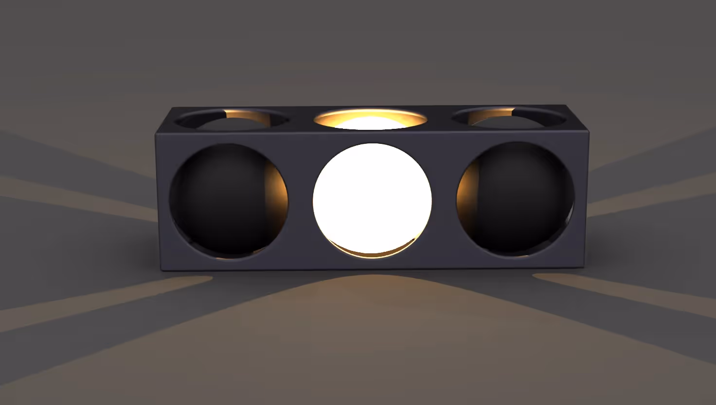

Emil Rindell

Jonas Bryntesson

Henrik Andersson
2022-07-20
Emil Rindell
Jonas Bryntesson
Henrik Andersson
2022-07-20
The term "Rendering" in the 3D world is, in short, a process of creating a realistic image from a 3D model.
There is also something called real-time rendering, which is a real-time rendering, meaning that shadows and reflections appear while you are modeling. A simple overview of the process is that a 3D model is created in a 3D modeling software then materials and colors are applied. Light sources are added and cameras are set up. The principle is actually somewhat comparable to a professional photography of a product in a photo studio.
In the past, it has been quite complicated to get into this world, but developments have progressed and the programs have become more user-friendly and easier to understand, but still advanced enough for those who really go into depth. There is both separate software for rendering but also implemented in both CAD and surface modeling software.
In this post we will focus on the image editing tools that are built into IRONCAD and in part 2 we will take a look at the third party software KeyShot that is becoming increasingly popular with our users.
Load the coffee maker because here we go!
IRONCAD has an advanced built-in rendering engine based on code from the YafaRay rendering engine that follows general image rendering standards. The rendered image is placed in a separate CPU thread and in its own window. This means that you can continue working in the 3D scene while the image is rendered in the background.
The rendering engine has a lot of settings and possibilities that can be a bit difficult to understand if you lack basic information and knowledge about how an image should be rendered. But hopefully you will have a broader understanding after this post.
A tip here is to print out the glossary at the end of the post, which can be useful to fall back on to keep up with the text.
When rendering images, it is important to recognize that the two biggest factors that affect the final outcome of the image are light and materials, with light playing the biggest role here. Light affects the colors, shading, reflections and refractions of each object in the scene.
Global Illumination ( GI ) is a concept in rendering that means you don't really need to work with separate light sources (although it is needed in some cases). GI allows you to get an even and nice lighting throughout the scene. The principle is actually quite simple where GI is a basic natural light in the 3D scene. Imagine an object on a table and without any lights directly pointed at it, you can see the object thanks to the natural light and that's exactly what GI stands for.
GI light is like a large sphere that emits light from all directions and edges towards the center of the sphere. As a user, in IRONCAD it is quite easy to set up the natural light. But GI light can also, with certain settings, be very computationally intensive which means that the rendering will take longer to produce.
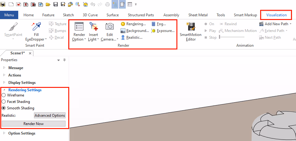
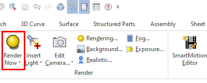
The rendering tools can be found under the tab Visualization and under Render-group. You can also access the settings via Property Browser:
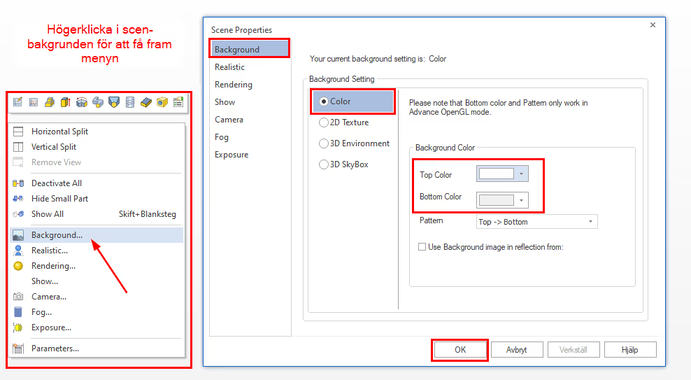
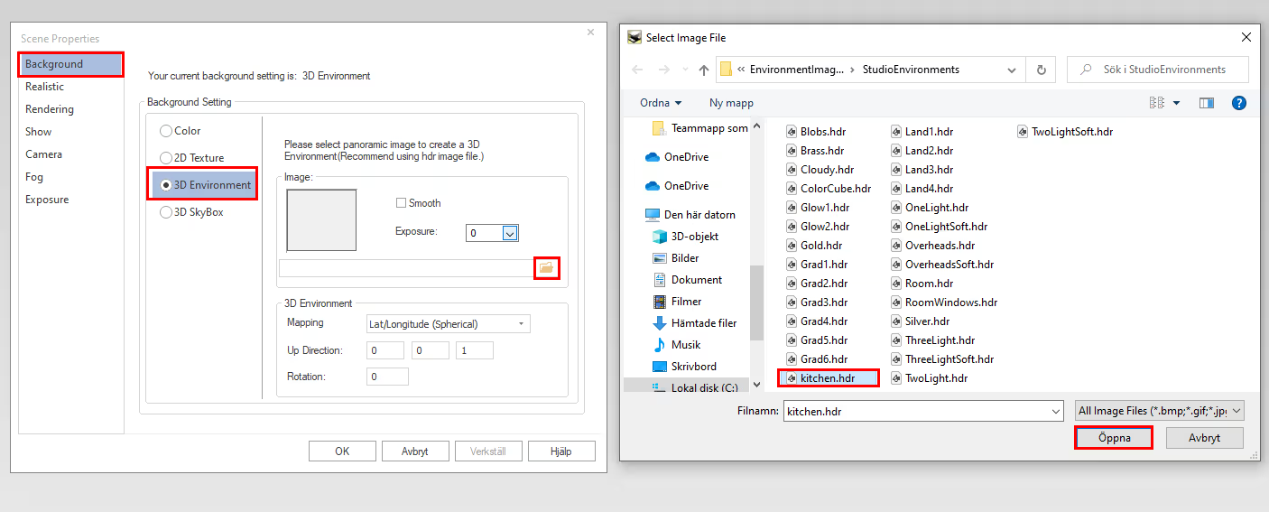
First of all, we recommend that you set a white colored background. This will make it easier to get a good result that does not affect the GI light (the color of the background will be the color of our GI light). Right click in the scene background followed by Background and Color. Then set Top and Bottom Color to white followed by OK.
To create a more realistic light, you can use a HDR (called 3D Environment in IRONCAD). An HDR(also called HDRI) image is usually a real photograph taken with a special technique, but can also be an image consisting of colors (usually black and white or grayscale) with white dots, rectangles and circles. The image itself acts as a light setter with GI, where the content of the image is reproduced in a natural way on your object.
Select the 3D Environment option followed by open and select, for example, the Kitchen.hdr file followed by OK. The folder contains a basic set of HDR images included in the IRONCAD installation, located at this path
C:\ProgramFiles\IronCAD \"version"\Images\EnvironmentImages\StudioEnvironments
In addition, there are many websites where you can download images for free or buy them.
Here you can find more HDR images.
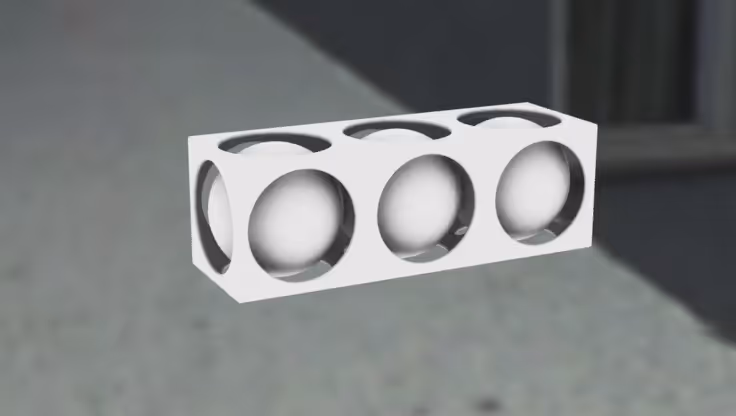
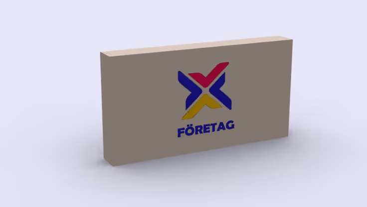
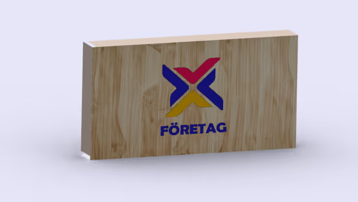
Here we have rendered an image of the model with an HDR image in the background.
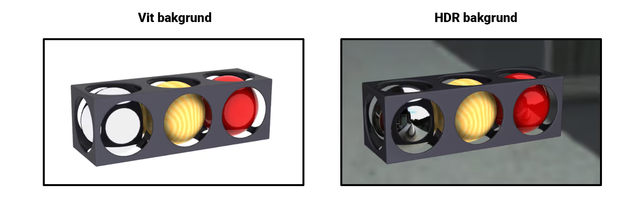
If we now compare the images, we see no direct difference between the images other than the background has changed. As I said, an HDR image can be used as a quick and easy way to change the feel of the image. But the images still look quite dull and boring. That's because we haven't added any material properties to our batches.
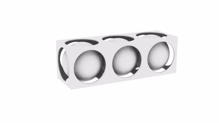
By influencing the properties of the materials in the image, we see the effect of the HDR image more clearly and the images take on more life. But even the image that was completely white in the background becomes completely different. White backgrounds can therefore be very useful when you want a simple and stylish visualization of a product.
But can I get a white background but keep the reflections in the material? Of course you can!
Then we use something called an Alpha Mask (image removal). By using an alpha mask, the background is "cut" away and with the help of an image editing program (Photoshop etc) we can add exactly what image or color we want instead. Not all file formats support alpha mask (e.g. *.jpg etc.) then we must instead choose *.png as the file format to use the function. More about this later in the post.
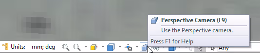
It is very important before we start rendering that the 3D scene has "Perspective" enabled (F9) in the 3D scene. If we don't have it, the rendering will take much longer to complete. The rendering engine calculates virtual "photons" (light particles) that bounce off the surface of the model and the camera's perspective is critical as the rendering will be completed more accurately and faster.
To make good use of GI lighting, we also recommend turning off all other light sources to begin with. It is better to start with a global light and then work your way forward with additional light sources. The preset light sources in the scene will cast sharp shadows and other unexpected effects.
Below we have a picture with GI and extra light sources, here we see for example that the light coming from the front is too bright / strong. As mentioned, start by turning off all other light sources to begin with and then experiment with extra light.

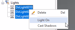
Select the lights under Lights in the history tree. Then right-click on them and uncheck Light On.
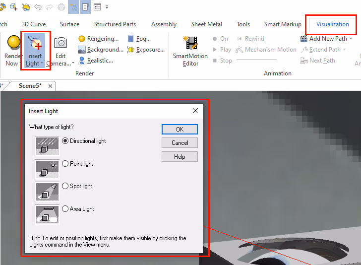
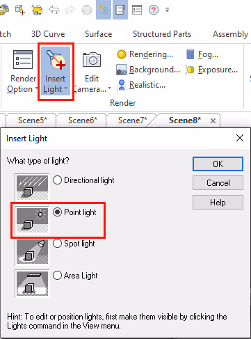
If you want to experiment with extra light sources, you can find them under the Visualization tab followed by Insert Light.
Now that you have gotten a brief overview of lighting, let's go through some materials to find more realism and depth in the image. The absolute fastest way to apply material is to drag and drop it from a catalog. IRONCAD contains a variety of catalogs with material but most of them are not opened by default.
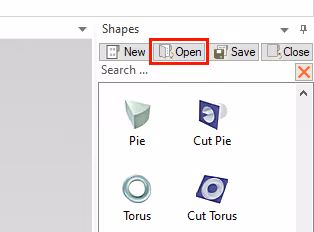
Click on the Open button above the catalogs and open the \Scene folder there, then hold down the [Ctrl] key and click with the left mouse button on these five directory files: AdvMaterial.icc, AdvWood.icc, Materials.icc, Metal.icc and Specular BRDF.icc. Open the files.
If you can't find the catalogs, you can download them here: Materials.
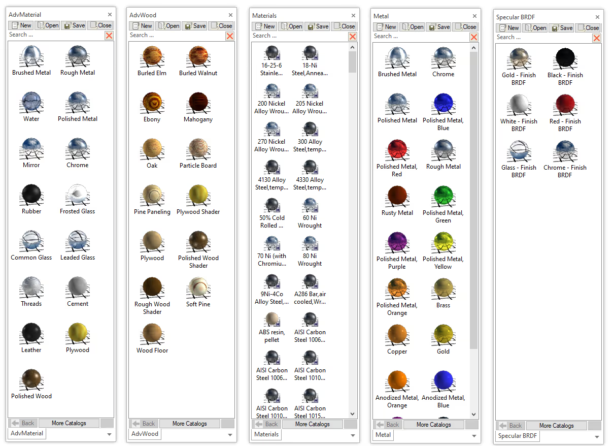
Hereyou can see the content of these five catalogs:
When a material is applied to a part or assembly, you will find the settings under Smart Paint Settings. Some of the settings are also visible under Property Browser for the selected part.
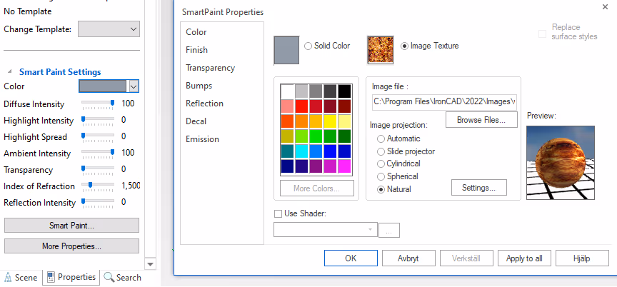
Under Color-properties you control the colors of the part, which is also accessed under Property Browser by a highlighted part or (green highlighted) surface.
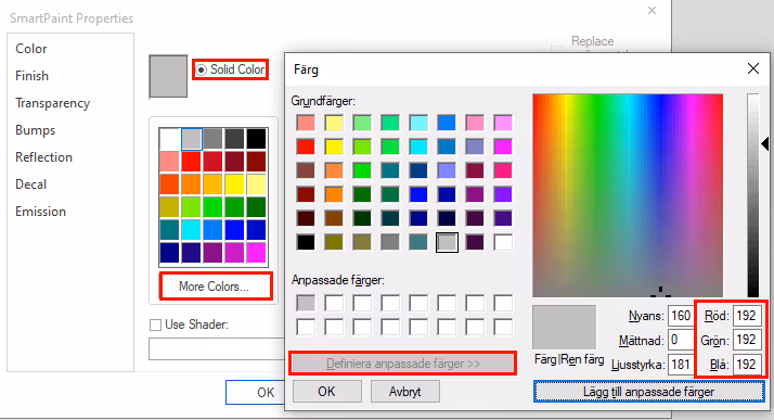
It is possible to choose from more colors than the default colors shown in the palette. To do so, click on More Colors. By then clicking on Define custom colors you can also choose to enter a custom RGB color.
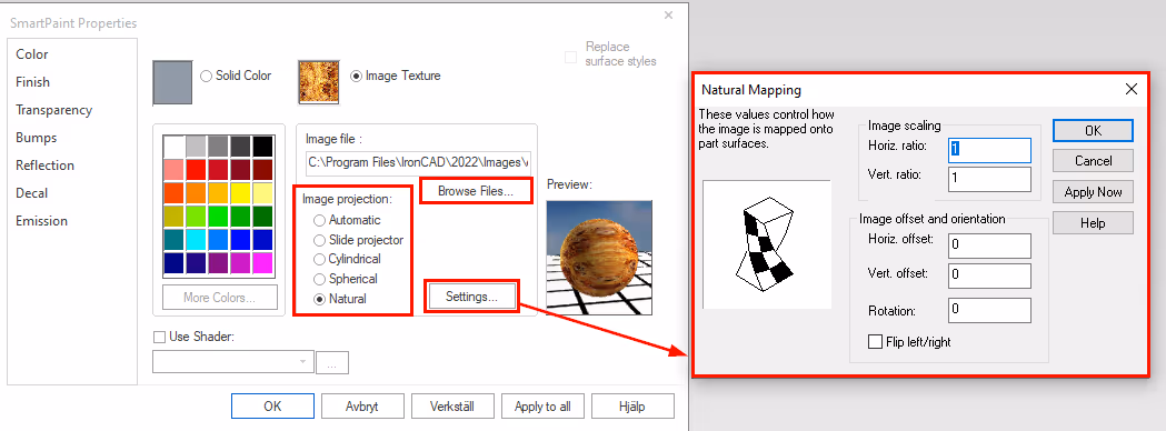
Instead of using a color, it is possible to project an image in the form of a texture on a part or surface. Here you can either drag a preset image from a catalog or choose to project your own image by clicking Browse.
Under Image projection you control how the texture is applied (also called "mapped") to the object or surface, which differs depending on the shape of the surface (spherical, cylindrical or flat). Naturalprojection is the most common for medium-sized surfaces/parts. Under each image projection there are settings (Settings) where you can both scale and rotate the image. Many times you need to go in and change here to get your texture exactly as you want it.
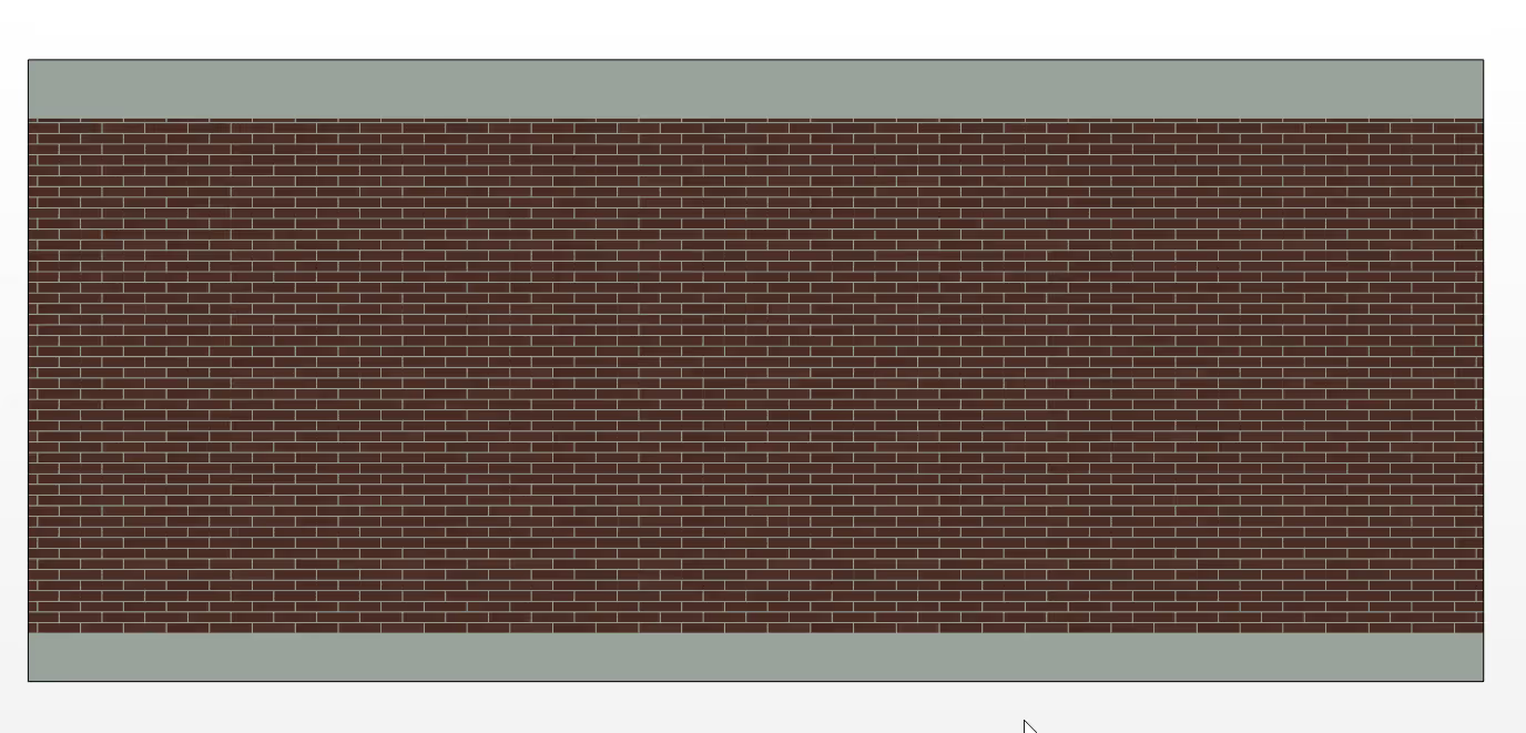
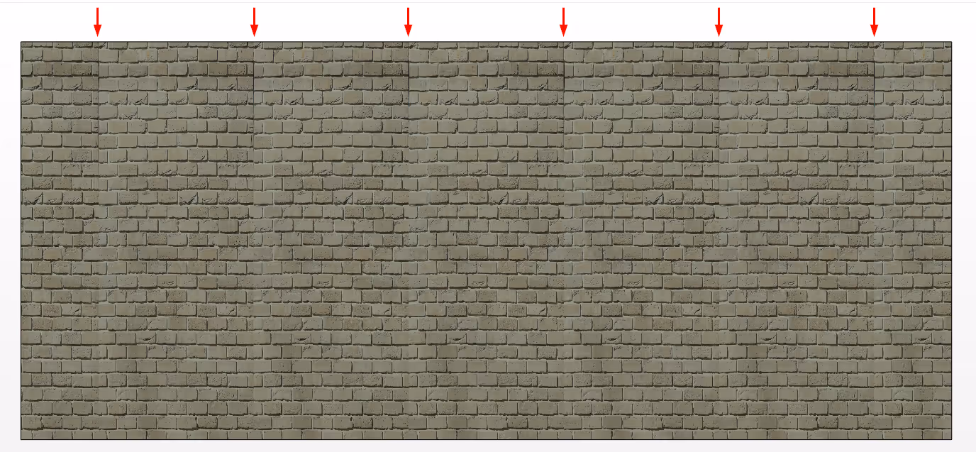
Tiled image also called Seamless is a concept in the world of rendering that means that you have an image without a seam. These types of images can be good to use when you want to map a surface that should not have any image joints, such as a lawn or a brick wall. The images are applied in the same way as above, the only difference is how the image is constructed.
The image below is a good example of an image that is seamless.
This image is mapped just like the one above but is not constructed as a seamless image. Here you can clearly see a seam in the image. So to create more realistic and consistent images, aim for seamless textures where needed.
As with HDR images, there is a plethora of websites offering both buy one get one free images. A good site with free images can be found at here and if you are looking for seamless images like the example above, search for Seamless or Tiled textures for example Google.
Instead of using textures, you can use a shader. You can roughly explain it as a "dynamic pattern". Based on parameters, you create different shapes or effects, for example you can use a shader to get an effect of a surface painted in a metallic color or build up your own veins in wood. This is something that requires a little experimentation but is relatively easy to get into if you want to. The effect of a shader is shown when the rendering is complete.
Instead of building a completely new shader from scratch, it is much easier to edit an existing one and modify the parameters until you get the desired result.
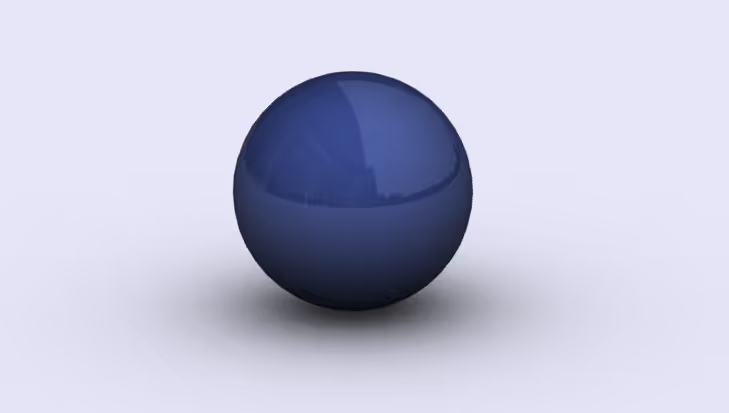
Here we have used a Multi-Layer Metallic Shader without affecting the default values:
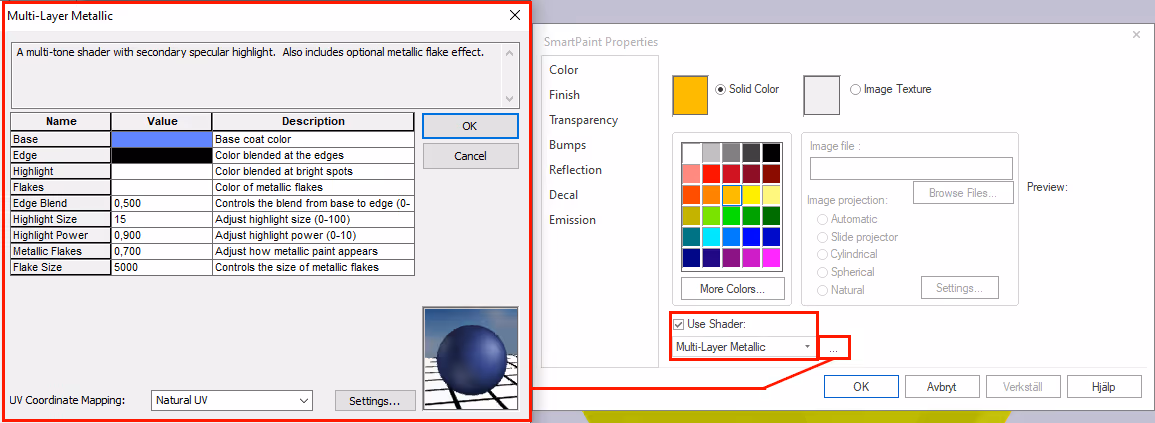
To use a shader you go into Smart Paint on the surface or part then check the Use Shader then click the down arrow to select a shader to start from. In this case we have chosen a Multi-Layer Metallic. If you then press the three dots, you will open up the settings for the specific shader. Here it is then up to you as a user to modify your parameters until you achieve the desired result. The parameters differ depending on shader.
A tip is to read at description what each value does for something.
If you have experimented too much and want to reset your settings, it's easy to just drag and drop the original material on the surface or the part from the catalog with the Shader, and it will restore what you have done.
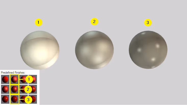
Under Finish-settings we find the effect of light on the surface or part. When we have no direct light or light sources other than GI, there is no change in how the light behaves on the surface. In this example, we have therefore chosen to render the image only with direct light instead of GI.
By looking at the sphere on the right, you can see how the light will spread over the surface depending on the parameters you change.
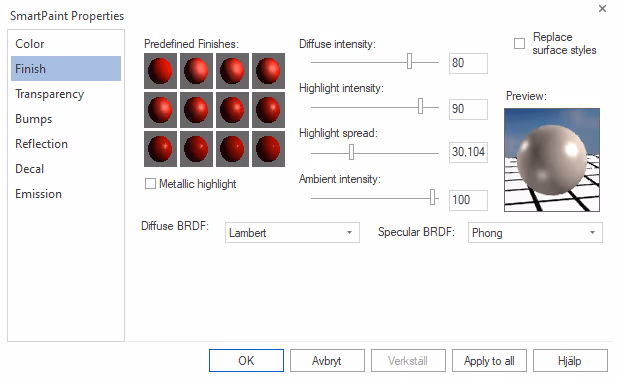
Under Predefined Finishes we find predefined values with different spreads on the light. Below we have rendered an image with direct light and used three different predefined light settings. As before, it is up to you as a user to modify the settings to suit your material or use some of the preset materials from the catalog explorer.
Under Finish we also have something called BRDF (Bidirectional Reflectance Distribution Function), but this functionality will not be discussed in this post. In short, it can further increase the realism of your rendering. Here you can see a movie that explains this in more detail:
When rendering something transparent, you should look at Transparency-tab under Smart Paint. Here we have preset parameters and also a simple slider, the more to the right the more transparency.
Index of refraction (The index of refraction represents the refraction of light rays as they pass between different materials. It is useful to find out the correct index of refraction for your material to get the most realistic rendering possible.
There are some refraction tables to be found on the web, here we have listed five materials with different refractive indices:
Vacuum: 1
Water: 1.33 (at 20°C)
Is: 1.31
Acrylic glass: 1.409-1.492 (at 20°C)
Window glass: 1.52 (at 20°C)
Silicone: 3.42-3.48 (at 20°C)
Diamond: 2.417 (at 20°C)
Sources: Read about the source here and this source here.
Anotherimportant thing to do when rendering transparent parts is to enable Render both sides of surface. Do this by going into the Part Properties on the part followed by the rendering tab and checking Render both sides of surface.

Another setting that may be useful to know is Ray Depth which can be accessed via Render Options>Image.
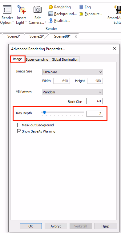
Ray Depth(ray depth) tells the user how many objects a ray can meet before it is considered "fully calculated". Hits can be propagated from reflections or refractions. This type of constraint must exist to prevent an infinite loop like two parallel mirrors facing each other(mirror 1 looking into mirror 2 looking back at mirror 1, etc.).
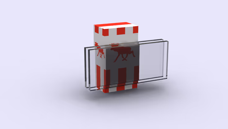
However, if the beam depth is too low, it will "terminate" too early, resulting in a background on the glass where a different geometry was expected. The default value in IRONCAD is 4, which is sufficient in simpler scenes but if there are multiple layers of transparency this value must be manually increased.
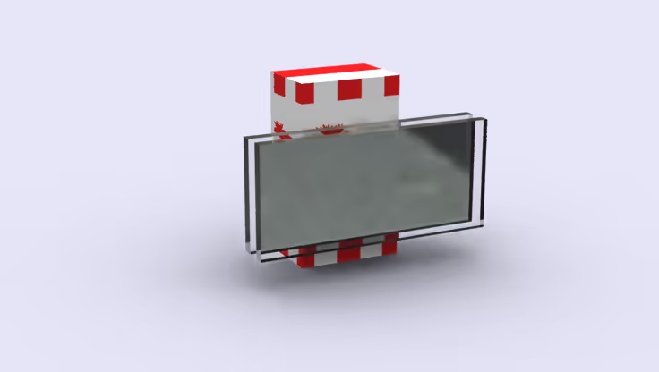
For example - if we look at an object through a window with a single pane that is rendered as two-sided, then a value of 3 in Ray Depth is appropriate. The ray enters the glass through the exit glass and hits the object, allowing us to see the object. If you look through a double-glazed window, you need a value of 5. If you look through a stack of two double-glazed windows, you need a value of 9, etc.
Ray Depth=2
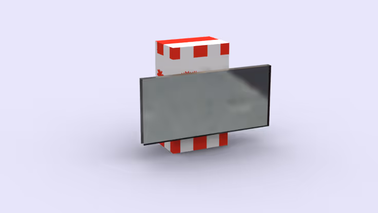
Ray Depth=4
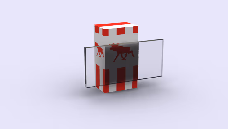
Ray Depth=4
Ray Depth=6
Bumps (also called "bump mapping") is a special technique for simulating bumps in the surface of a part. You actually put images in different layers on a surface where the underlying image creates a bump on the surface above. By default, bump maps in IRONCAD are ignored when rendering so if you want to use these, we must first make a setting under GI to make these visible.
Click on the arrow below Render Now and you will see Render Options. There you choose to go to the tab Global Illumination and uncheck Ignore Bump Normals followed by OK.

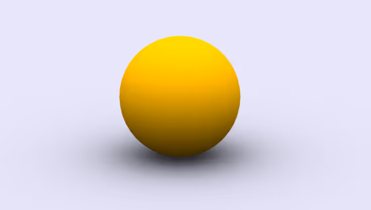
Below we see a yellow rendered sphere that does not contain a bump folder:
Under Smart Paint in IRONCAD we will find Bumps. You can use any image as a bump folder but a good guideline is to have a black and white image to get a lot of contrast in our bumps.
Click on the Make bumps from image and select the image you want to use as the bump folder. Here we also see Image projection where we control how the bump map should be projected onto the surface. In this case we choose Spherical because we have a sphere like part. Bump height you control how strong the bump should be. Here you can choose a positive or negative value where the former simulates elevations in the material.
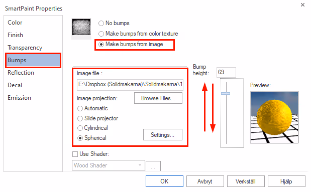
When you then press OK , you will not see any change in the material, but we need to render it to see the result.
Press CTRL+R (keyboard shortcut to start a render) or select Render Now under Visualization to start the rendering.
Here we can now clearly see how our Bumpmap has affected the surface:

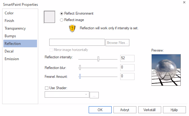
Under the Reflection tab we find settings to make a material reflect surrounding objects, environment and light. Basically, all materials reflect light to some degree, where the lack of reflections in a material is related to microscopic unevenness in the material. By dragging the slider Reflection intensity slider to the right, we increase the reflections in the material, how much light is reflected by the material we will see on the sphere to the right.
Experimenting with reflection values is very rewarding as you quickly gain realism in the image. The important thing is to try to find out how much light the real material actually reflects in reality.
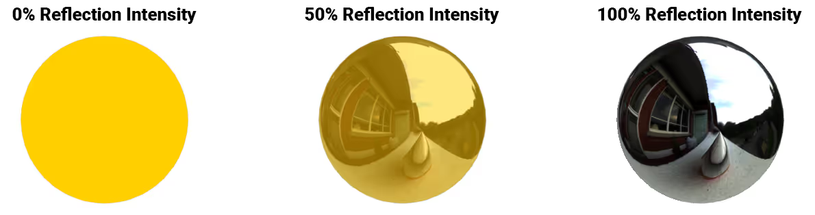
Below we see three simple spheres where we have only set Reflection intensity to 0, 50 and 100%. By having the default selection Reflect Environment enabled, we get reflections from the HDR image in the background and from surrounding objects(which we do not have in this particular scene).
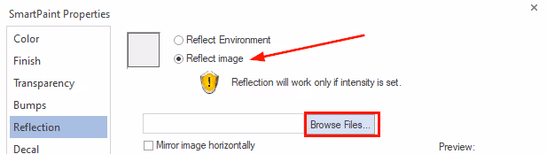
In some cases you want to reflect some other image in the material than the background, then you can choose the option Reflect image which means that you can choose any image to be reflected in that particular part.
Below we see an example where object A on the left uses the option Reflect Environment while object B on the right uses Reflect Image.
Note how object B still reflects surrounding objects (B) in the 3D scene through the setting Reflect Image. It is only the "environment reflected in the image" that has changed without changing the 3D scene background.

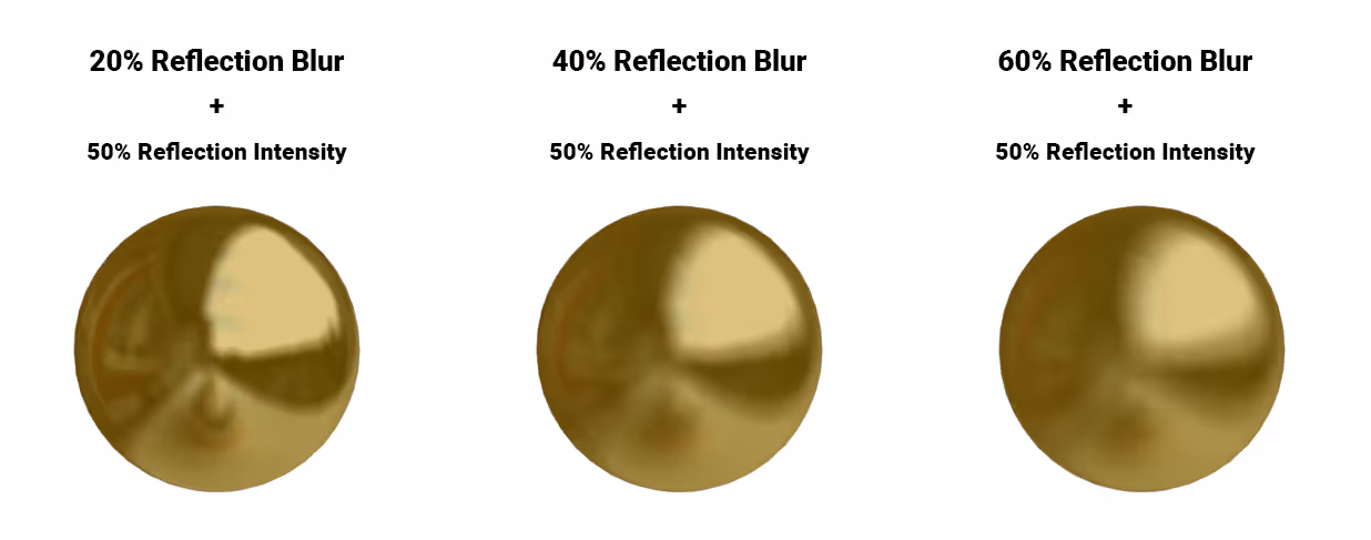
If you want to create more blur, you can use Reflection Blur in combination with Reflection Intensity to create more matte reflections. Use the preview on the right to see how the reflections are affected in the material.
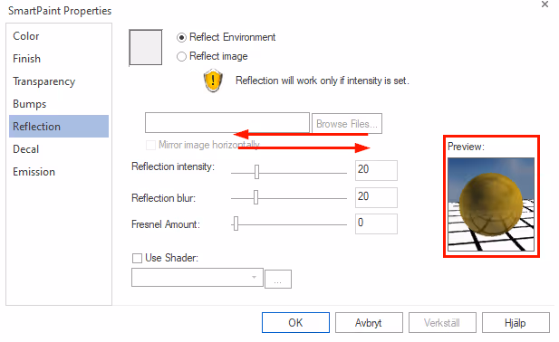
Below is an example of how we have combined these two functions.
Under Reflection we also have something called the Fresnel Amount. this functionality we will not address in this post. Here you can watch a video explaining this in more detail instead:
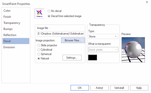
Decal i Smart Paint is used to apply a decal/logo to a surface. Mapping decals is essentially the same methodology as mapping textures, but with an option to build up layers in the image.
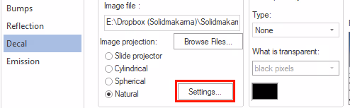
In short, it works like putting a sticker on a surface. The ideal is to have a *.png image with an Alpha Mask, an exposed image simply. The principle is simple to apply: select an image by pressing Browse Files, followed by how the image should be projected on the surface. In this case we have a flat surface and will use Natural.
This is what it looked like when we had just added a sticker without doing anything underneath Settings:
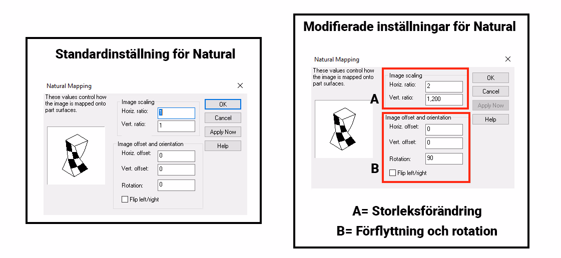
This is not exactly how we wanted the image, but we want to address this because this is something you often see when you start mapping decals. The image can be misoriented and overlaid over the entire surface. If we now instead go into Settings and change the values, we will get a different result.
Here you can see the default settings and what we changed:
The result is now like a sticker on the surface:
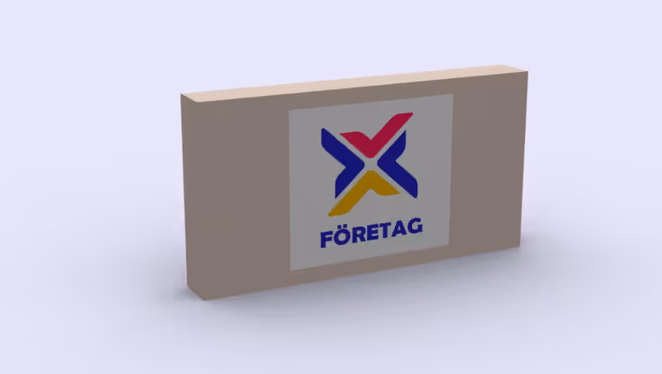
In the above image, we have used an image that has *.jpg as the file format, but the *.jpg format does not support Alpha Mask and therefore a background appears on our decal, in this case white. If we want the sticker to be exposed / cut out, we must use an image in the *.png format that uses an Alpha Mask.
When we apply an image with an Alpha Mask, we also have to modify the Transparency the settings under Decal. Here we chose Type: see-through and What is transparent: black pixels.
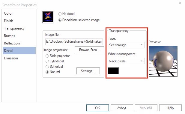
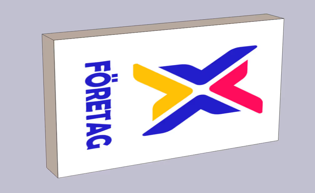
This is what it would look like if we used our image that was exposed:
Experiment with the settings and you'll quickly understand how to make it work for your image. Again, use the sphere on the right for a preview of how it will look with your settings. Now that we've added this image as a decal, we can map any background or color behind the decal. This is then mapped via the tab Color i Smart Paint. The background of the decal will appear after the rendering is complete.
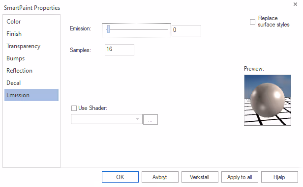
Emission i Smart Paint is a method to create materials that glow and emit a light. Change the bar Emission bar to make the material glow with the desired intensity and change Sampels for how many times this will be calculated by the computer, the higher Samples the more accurate the calculation of the light emitted.
NOTE! We recommend to use both these settings sparingly as it very quickly affects the rendering time.
In the example below we see how the material starts to glow the higher Issue value it gets.
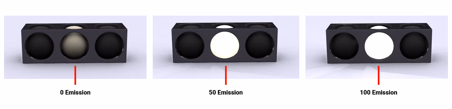
But one thing worth noting is that we don't actually get any direct light scattering, more than a sense that the material is glowing. Especially if you look at the surrounding geometry. It's actually just like that Emission works. If we want a real light source, we have to add one ourselves.
In the case below, we added a Point Light which you can find under Insert Light i Visualization tab.
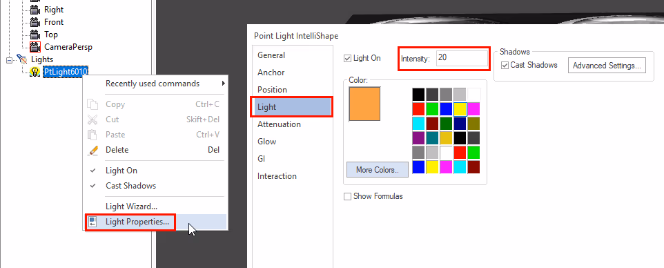
We then placed the light source using TriBall in the centre of our sphere which is in the middle. Then right-click on the light source below in the Lights in the story tree and select Light Properties followed by Light and Intensity where you change the brightness of the light. There are a variety of other light settings. We recommend that you go in and try it out for yourself to see what it will look like when you modify certain settings.
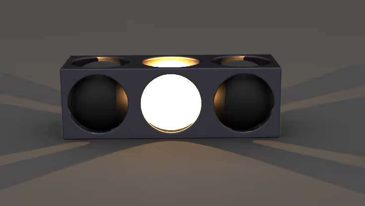
By combining issuance with a Point Light we can get a much more realistic glow that actually scatters light in our model:
Here you can download the scene above and see how we did it in more detail(created in v2022 PU1SP1):
Under Render Options you will find all the settings for the rendering engine where you control how the image is built up and how the light is controlled.
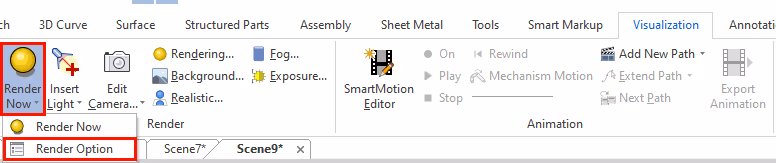
If you are using the classic interface(Toolbar UI), make sure you can see Render-tools. The yellow sphere on the right is Render Now which will start your rendering. The white button on the left is Render Options.
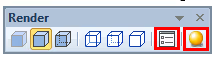
Render Options is also hidden under Render Now button in the Ribbon Bar border.
The first tab under Render Options controls the size of the image and Fill Pattern, which means how the image should be calculated in its render window and the size of the blocks, the pattern of the image on the right:
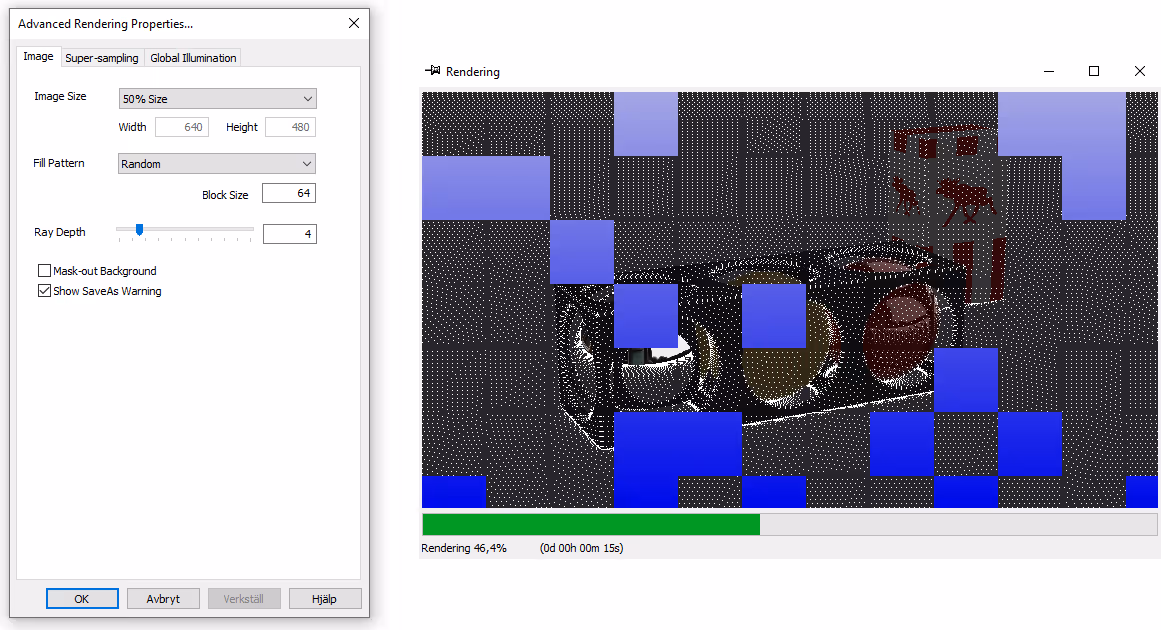
Ray Depth value has been covered earlier in the post so we refer to that part of the post.
To save your image with an exposed background (Alpha Mask), make sure that you do not have any other object, floor etc. obscuring the background.
Startby right-clicking on your rendering when it is ready and select Save As.
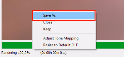
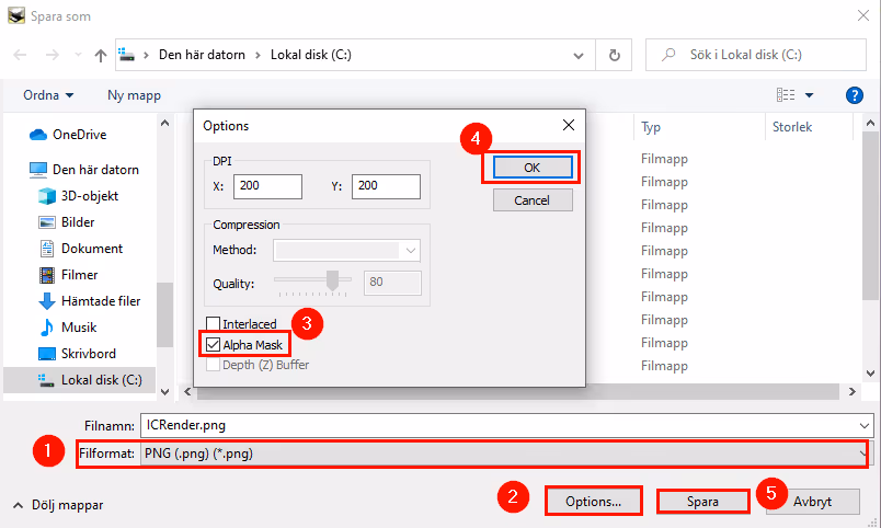
Then select *.PNG as the file format, followed by Options, then check the box Alpha Mask and then press OK and Save.
Super-Sampling which is a form of antialiasing and can be described as a methodology to remove "aliasing" which is choppy and "pixelated" edges from the rendered image.
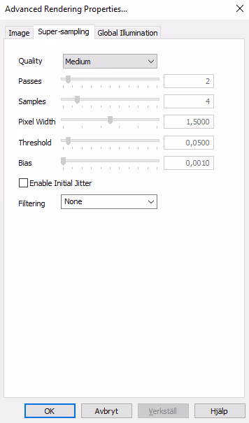
We will not address this in this post but refer to this film instead:
At the beginning of this post, we covered a bit about what GI is and how to use it. The settings for Global Illumination in IRONCAD can be found here:

The area around GI is large and broad and almost requires its own separate guide for deeper explanation. The concept is not unique to IRONCAD, like many other things covered in this guide, but a general one in rendering and animation. This movie will give you a broad understanding if you really want to geek out on the world of rendering and GI:
If you want more basic knowledge about how rendering works in IRONCAD, we recommend that you look through our basic course material and then use this guide as a complement and deeper explanation.
Here you can find our free training material on rendering in IRONCAD:
KeyShot is an add-on to IRONCAD that can create incredible renderings and animations quickly and easily. The link to IRONCAD allows you to transfer the model to KeyShot at the touch of a button, where the user can add material effects, textures, background themes and lighting effects. The image is rendered in real time, so you can quickly see the effect of the change you have just made. Creating photorealistic product images and animations has never been easier.
We offer KeyShot Add on to both IRONCAD and INOVATE.
Here you can read a guide to rendering images in KeyShot.
Answer: Here we publish tips, guides, news and solutions for those who work with IRONCAD and Design Data Manager (DDM). The blog covers everything from basic functions to advanced workflows, helping you to optimize your design work. You'll find examples of smart shortcuts, practical instructions, solutions to common problems, and best practices for product design, mechanical design, and product data management.
Answer: Our guides and tips are designed for both beginners and experienced CAD users. They are aimed at designers, engineers and project managers who want to work more efficiently with IRONCAD and DDM, improve the design process, reduce mistakes and save time in product development.
Answer: We regularly publish new articles when the software is updated, when new features are introduced, or when our users ask for solutions to specific problems. The blog is therefore a reliable source for keeping up to date and getting tips that make everyday CAD work easier.
Answer: Many of our instructions and tips work in multiple versions, but we clearly indicate if an article applies to a specific version. We strive to make the content useful for older versions as well, and also provide recommendations on how to adapt workflows to the version you are using.
Answer: Absolutely! If you can't find the solution in the blog, you can contact our technical support via solidmakarna.support. Our experts will help you with everything from installation and configuration to advanced features in IRONCAD and DDM, so you can solve problems quickly and efficiently.
Answer: Yes! We appreciate suggestions from our users. If you have questions, tips or want us to address a specific issue in IRONCAD or DDM , please contact us via our contact form and we will prioritize relevant topics in future posts.
Answer: The blog contains, among other things:
Practical step-by-step guides to help you use IRONCAD and DDM more effectively.
Productivity and workflow tips for faster design and construction.
Solutions to common problems encountered by users in CAD programs.
Updates and news on new features, versions and improvements.
Best practices for data management and project organization in DDM.
Answer: All tips and guides are directly applicable in daily work. For example, you can use shortcuts and smart features in IRONCAD to speed up modeling, structure files better in Design Data Manager, or follow our step-by-step solutions for specific problems that often come up in design projects.
Answer: We strive to ensure that all guides and tips are relevant to the latest versions of IRONCAD and DDM. We also clearly mark when a post applies to an older version, so you always know if the instruction is directly applicable to your system.
Answer: Yes! Many of our users share the articles with colleagues and use them as internal training materials. The blog is a great complement to formal training and helps teams learn features faster, avoid mistakes, and standardize workflows in IRONCAD and DDM.