Looks like you don't have ESC button on your device
Download IronCAD DCS
Choose one of the following options
trial versionHas a license
Looks like you don't have ESC button on your device
Choose one of the following options
trial versionHas a license

Emil Rindell

Jonas Bryntesson

Henrik Andersson
2023-04-27
Emil Rindell
Jonas Bryntesson
Henrik Andersson
2023-04-27
When you import 2D DWG or DXF drawings to the cross section (sketch) in IRONCAD or when you open them in Draft (CAXA) you can choose between two tabs; Model and Layout. What is the difference between these two?
Unlike IRONCAD and most other 3D CAD systems, the most common "AutoCAD-like" 2D CAD software handles both its 2D and possibly line-based 3D models in a single file. The most common file format for this type of 2D CAD system is the DWG format.
When and why should you choose between the Model and Layout tabs? It's really quite simple!
In these types of 2D CAD systems, the Model tab is the "environment" where 2D (and possibly line-based 3D models) are always drawn in scale 1:1 and since CAXA Draft is such a type of 2D CAD system, the Model tab is the place where you draw your 2D CAD geometries. This can be explained as the equivalent of IRONCAD's 3D environment.
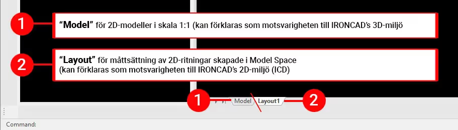
The Layout tab can then be explained as the equivalent of IRONCAD's 2D drawing environment (ICD). This is mainly for depicting 2D models (created in CAXA) or 3D models (created in IRONCAD) on a 2D drawing. Therefore, the Layout tab is also where you have your drawing frames, drawing header, bill of materials (BOM), dimensioning views, etc.
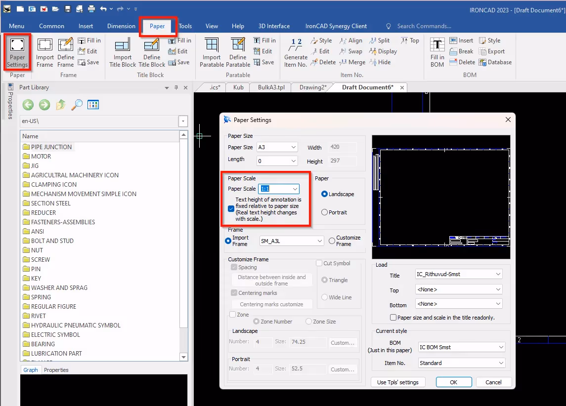
In order to generate views from 2D geometries drawn in the Model tab, Viewports (of 2D CAD geometries) are created in the Layout tab. There(Layout) it is also important that the paper scale of the drawing is set to 1:1 scale, because the size and scale is controlled individually on a view(Viewport) in a similar way as in ICD.
The control of thePaper Scale can be found via the Paper Settings button on the Paper tab.
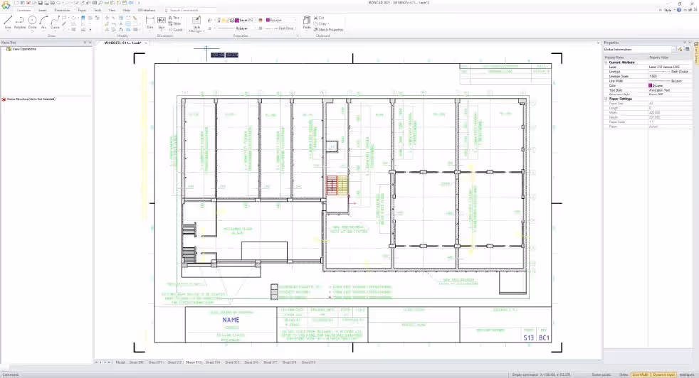
This is what a typical 2D design of a mezzanine floor might look like under the Model tab.
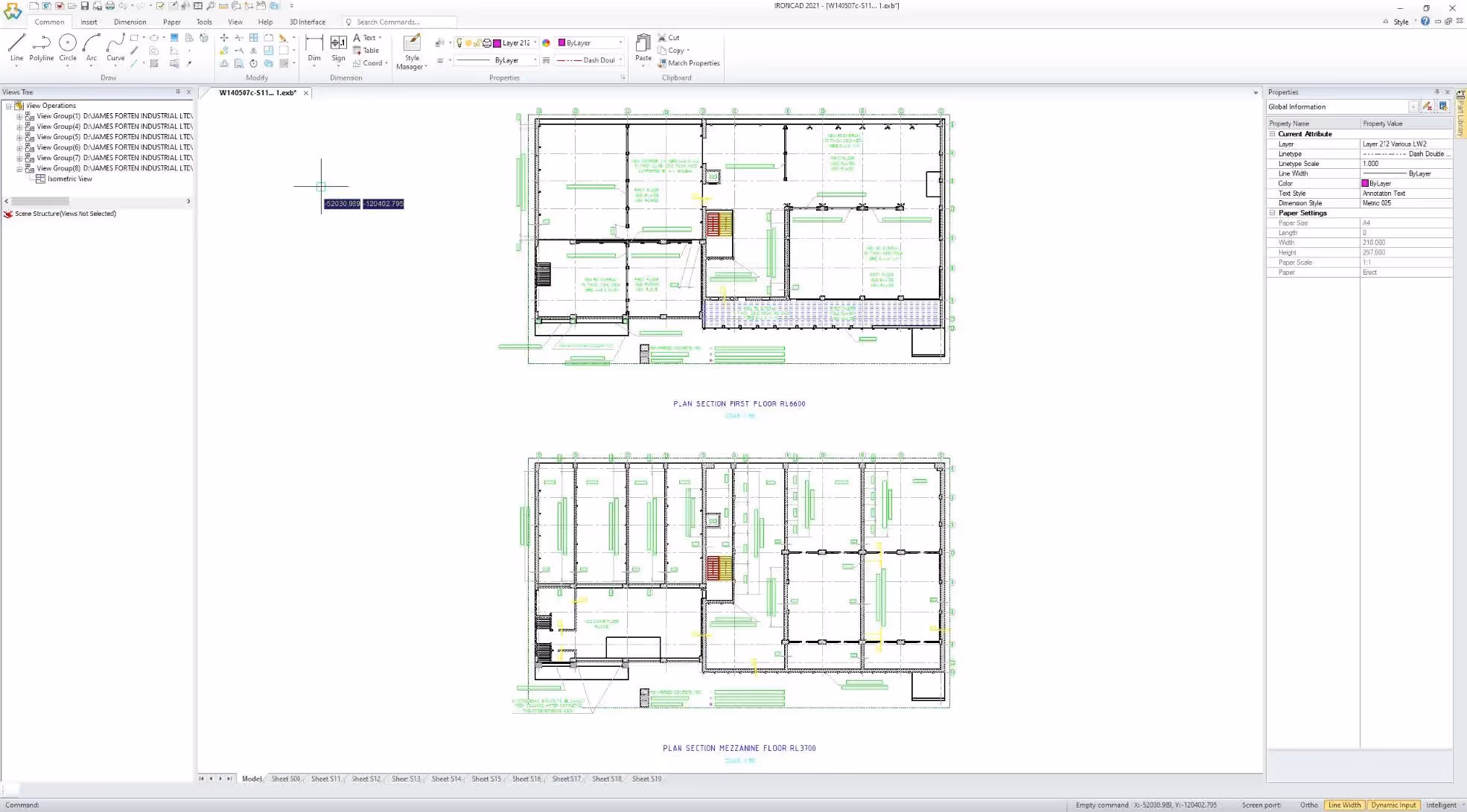
TIP! You can change the background color from black (default) to any color in CAXA Draft. The example above uses a white background instead of black. Click here to see how to do this.
In CAXA Draft , as mentioned, you use Viewports when you want to depict a 2D model in the Layout tab, but which you have drawn in the Model tab.
This is what it looks like when we set up aViewport under the Layout tab (from the mezzanine floor designed under the Model tab), where there is also a BOM and drawing frame etc.
In a similar way, 3D models from IRONCAD's 3D scene are depicted as Generated Views under the Layout tab. The difference there is that Generated Views always use 1:1 scale and instead you scale up or down the drawing frame (the scale of the paper size) around the views through Paper Scale (see above).
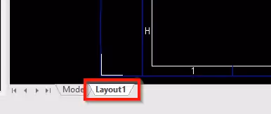
To depict a 3D model created in IRONCAD , first go to the Layout tab at the bottom left.
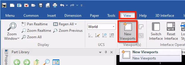
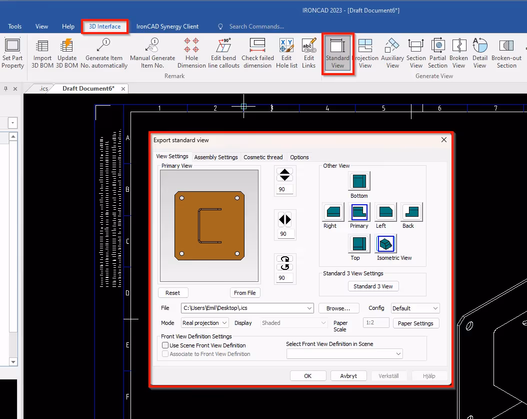
Next, launch the Standard View command to create a new set of drawing views. The button displays the 3D Interface tab.
This is what a 3D model produced by IRONCAD's 3D scene and depicted in CAXA Draft 2D can look like.
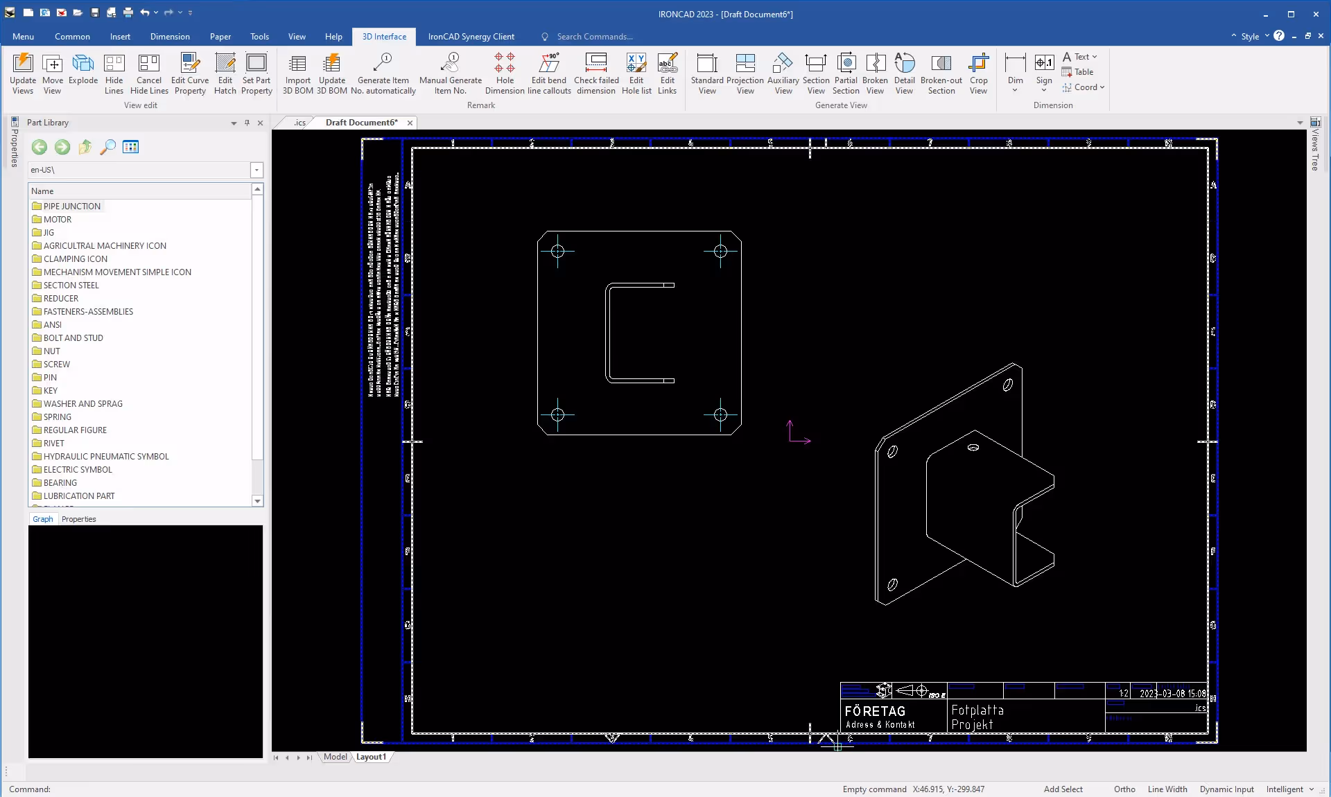
Notice here that the twoGenerated Views actually use a 1:1 scale, but the drawing head still shows a 1:2 scale, at the bottom right. This is because thePaper Scale is set to 1:2, which means that the paper is scaled up twice as large to accommodate the two views (which can then be said to be 1:2 scale) on an A3 paper. This is something that is taken into account when printing to paper or to a PDF document.
The golden rule is to always create your views under the Layout tab, but there are some exceptions when it may be beneficial to actually create your view under the Model tab instead.
Sometimes you need to show different parts of a 3D model on a 2D drawing. One way to do this is to create "sectional views" of the model, that is, to show how the model would look if you cut it in different places. To do this, you can first depict the 3D model under the Model tab. Then you can use a Section View (under the 3D Interface tab) to create different section views of the 3D model. These section views can be placed under the Model tab.
In order to depict the section views on the actual "2D drawing" (i.e. the Layout tab), you can add so-calledViewports. Each Viewport then shows a specific section view in the Model tab.
This movie shows an example of this (NB, no sound):
Answer: Here we publish tips, guides, news and solutions for those who work with IRONCAD and Design Data Manager (DDM). The blog covers everything from basic functions to advanced workflows, helping you to optimize your design work. You'll find examples of smart shortcuts, practical instructions, solutions to common problems, and best practices for product design, mechanical design, and product data management.
Answer: Our guides and tips are designed for both beginners and experienced CAD users. They are aimed at designers, engineers and project managers who want to work more efficiently with IRONCAD and DDM, improve the design process, reduce mistakes and save time in product development.
Answer: We regularly publish new articles when the software is updated, when new features are introduced, or when our users ask for solutions to specific problems. The blog is therefore a reliable source for keeping up to date and getting tips that make everyday CAD work easier.
Answer: Many of our instructions and tips work in multiple versions, but we clearly indicate if an article applies to a specific version. We strive to make the content useful for older versions as well, and also provide recommendations on how to adapt workflows to the version you are using.
Answer: Absolutely! If you can't find the solution in the blog, you can contact our technical support via solidmakarna.support. Our experts will help you with everything from installation and configuration to advanced features in IRONCAD and DDM, so you can solve problems quickly and efficiently.
Answer: Yes! We appreciate suggestions from our users. If you have questions, tips or want us to address a specific issue in IRONCAD or DDM , please contact us via our contact form and we will prioritize relevant topics in future posts.
Answer: The blog contains, among other things:
Practical step-by-step guides to help you use IRONCAD and DDM more effectively.
Productivity and workflow tips for faster design and construction.
Solutions to common problems encountered by users in CAD programs.
Updates and news on new features, versions and improvements.
Best practices for data management and project organization in DDM.
Answer: All tips and guides are directly applicable in daily work. For example, you can use shortcuts and smart features in IRONCAD to speed up modeling, structure files better in Design Data Manager, or follow our step-by-step solutions for specific problems that often come up in design projects.
Answer: We strive to ensure that all guides and tips are relevant to the latest versions of IRONCAD and DDM. We also clearly mark when a post applies to an older version, so you always know if the instruction is directly applicable to your system.
Answer: Yes! Many of our users share the articles with colleagues and use them as internal training materials. The blog is a great complement to formal training and helps teams learn features faster, avoid mistakes, and standardize workflows in IRONCAD and DDM.