Looks like you don't have ESC button on your device
Download IronCAD DCS
Choose one of the following options
trial versionHas a license
Looks like you don't have ESC button on your device
Choose one of the following options
trial versionHas a license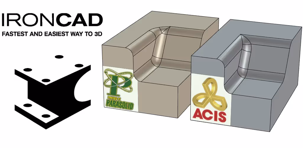

Emil Rindell

Jonas Bryntesson

Henrik Andersson
2023-09-08
Emil Rindell
Jonas Bryntesson
Henrik Andersson
2023-09-08
Parasolid and ACIS - the fact that IRONCAD uses two solid kernels simultaneously is not something you really notice in everyday work. In addition to simplifying certain complex steps "under the hood" without the ordinary user noticing it, it also means that the program can handle models that come from other completely different 3D CAD systems in a very good way. However, you may need to switch between the two in some situations, which is done with a simple push of a button.
A geometric modeling kernel (often called a solid kernel) is the software component (code) used in a 3D CAD system that defines how a 3D geometry is constructed. In order to produce a "correct topological 3D model", the solid kernel is used to mathematically describe what the 3D model looks like.
In the beginning, geometric solids were managed and calculated by each individual 3D CAD system, but in the 70s and 80s the solid kernel was commercialized, which for many developers instead became a ready-made component that could be licensed and "baked in" in their own 3D CAD system. There are today several companies (and even countries) that develop various competing solid kernels and which are used by many well-known or less well-known 3D CAD systems, where IRONCAD is unique in its kind as it uses (licenses) two parallel solid kernels at the same time! These two are;
Owned and developed by Siemens Digital Industries Software, it is today the dominant option among most CAD and CAM systems. Parasolid itself was originally developed at Cambridge, England, where it was first released in 1988 as a further development of the first commercially available solid kernel ROMULUS (released in 1978).
Owned and developed by Spatial Corp (part of French Dassault Systemes). ACIS was also developed from the early ROMULUS, by the same people, to be used in a new American CAM system developed by Spatial and to be released in the late 1980s.
Upon the release of the ACIS kernel in 1989, the company Hewlett-Packard was quick to license it for their UNIX and later DOS-based HP ME 3D CAD system, which was used for their completely revolutionary way of handling 3D models and which, in various ways, later became an important building block of what is today IRONCAD.
In the first versions, IRONCAD was based only on the ACIS kernel and only with IRONCAD version 3 (1999/2000) the Parasolid kernel was added by the R&D team simultaneously developing something called Kernel Collaboration. More on that later.
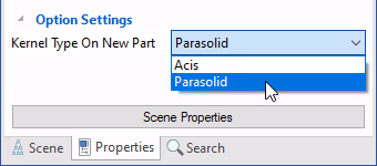
To determine which solid kernel will be "primary" in IRONCAD , you can click on the Properties tab in the bottom left of the 3D scene and switch between the two solid kernels. This determines which of them will be the "primary" solid kernel for the next new part created. However, this does not apply if you import files in the Parasolid (*.x_t) or ACIS (*.sat) file formats, as they will automatically use "their own" solid kernel.
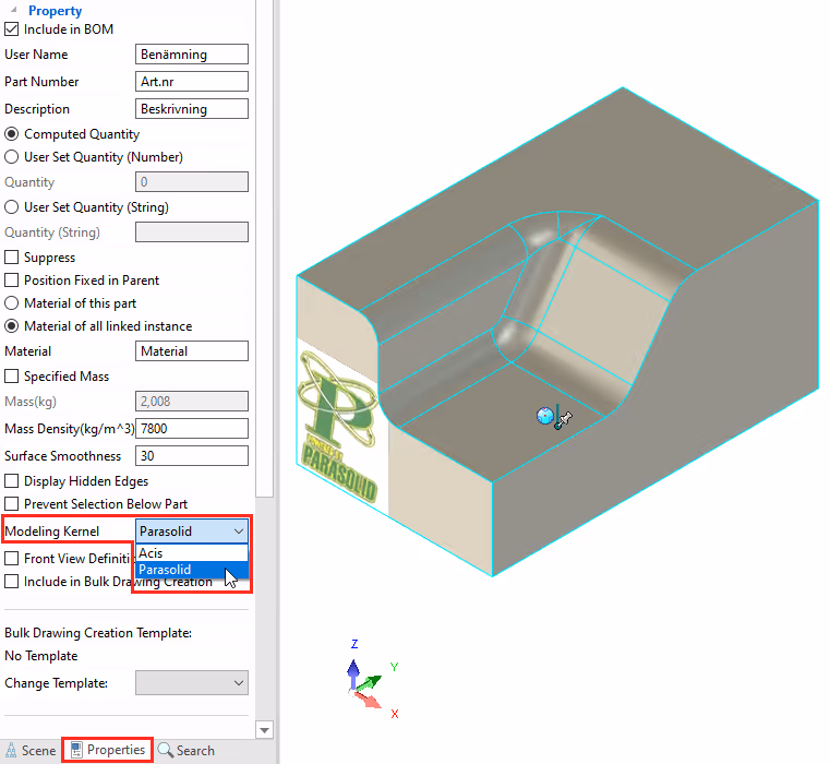
You can also subsequently switch between the two solid kernels for one or more parts at the same time. This also applies to one or more assemblies containing several objects.
If you work in a 3D CAD system that is based on one solid kernel, you may encounter problems when receiving and managing models from a 3D CAD system based on the other solid kernel. It is (so far) only IRONCAD that uses both the Parasolid and ACIS kernels simultaneously and the technology for handling models in this way, Kernel Collaboration, was developed by the R&D team in the late 90s.
As mentioned, a part primarily uses one solid kernel, but there are some situations where "geometric problems" are automatically fixed by the program through Kernel Collaboration, without the user even noticing it. This is especially true when creating or changing Modification Features such as Blend, Chamfer, Shell or using the Boolean operation command (merging parts) and when working withDirect Face Modeling. If Parasolid encounters a geometrically complex problem, the ACIS kernel immediately takes over and solves it "under the hood".
However, there are some situations where a limitation (or possibly a bug) in one solid kernel is not directly handled automatically, but you have to switch to the other solid kernel being "primary". One such example is "non-manifold".
There is a clear limitation with the Parasolid kernel, where something called "zero thickness" or "non-manifold" is a problem that can sometimes be encountered while modifying geometries. One example is if a cylindrical hole is laid tangent to a plane or tangent to another cylindrical surface. Another is if an edge line on one block is tangent to an edge line on another block. This means that models can suddenly appear "hollow" or give error messages or negatively affect the export or 2D drawing. The ACIS kernel was originally written in a way to better handle non-manifold, but there are also different types of limitations or problems with the ACIS kernel.
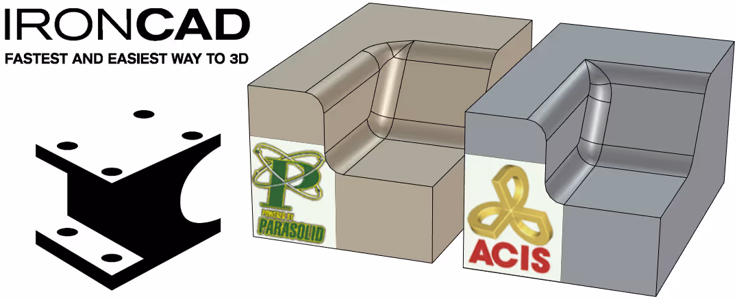
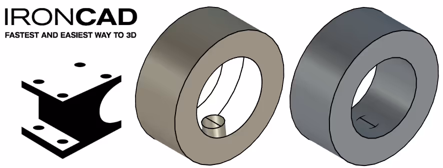
Here are some non-manifold examples of identical parts using one or the other solid kernel; Parasolid on the left, ACIS on the right.
First is a cylindrical hole that touches the contour of another cylindrical hole where the Parasolid kernel usually shows a "hollow" surface model-like part, while the ACIS kernel can handle this better.
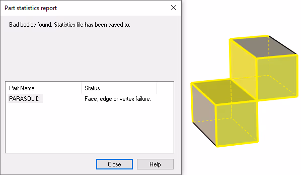
The same can be seen between two blocks where the borders between the blocks are touching each other. A position that you can end up in when, for example, pulling with Sizebox handles to snap one side to another. However, it is rare to actually make a model that is intended to use this mode, other than temporarily before more features are added or further changes are made. This is because a model that consists of a "non-manifold" in itself probably cannot be manufactured. The example with the two blocks below is therefore an exaggerated way of showing how the error can occur.
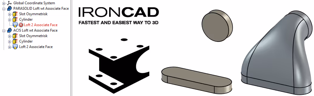
Another example is a Loft feature whose two cross-sections (sketches) on each side are associative with other features. The Parasolid kernel often has problems solving this as it becomes too tight between the shapes and as it has difficulty handling a property called Tangent Factor (how far should the shape be "pushed forward" before it "bends off" towards the next section). This usually works better with the ACIS kernel.
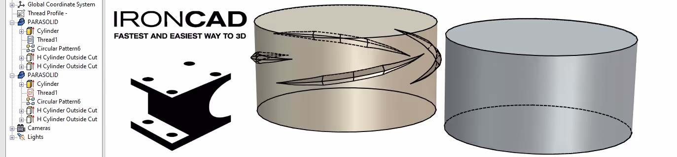
A final example is the opposite, where the Parasolid kernel fixes a shape that the ACIS kernel cannot. Usually this is due to small adjustments of properties and in this case there is no clear reason for what makes it work or not. Here you often need to switch between the two solid kernels and test your way around. The ACIS kernel also does not show all the settings that are possible with a Thread feature.
The program TransMagic has a longer and more technical description of this problem and how to deal with it to create correct solids.
The developers of TransMagic have also tried to simplify the concept (here taken from their blog post above): Manifold is a geometric topology term meaning: To allow disjointed lumps to exist in a single logical body. Non-manifold then means: All disjoint blobs must be their own logical body. Of course, that definition is often more confusing, so perhaps the best way to think about manifold and non-manifold is this: Manifold essentially means "manufacturable" and non-manifold means "non-manufacturable". In other words, manifold means: You can machine the shape of a single block of metal... where non-manifold means you can't machine from a single block of metal.
On IronCAD's user forum there are a couple of interesting threads, an older What Does Kernel Collaboration Mean? and a more recent thread with some examples Dual Geometric Modeling Kernels - Kernel Collaboration (Examples).
Finally, keep in mind that both of these solid kernels continue to evolve and what was once a truth may no longer be. Switching between the two is always something to consider as a possible solution when encountering a problem, even if it didn't work in a previous version.
Answer: Here we publish tips, guides, news and solutions for those who work with IRONCAD and Design Data Manager (DDM). The blog covers everything from basic functions to advanced workflows, helping you to optimize your design work. You'll find examples of smart shortcuts, practical instructions, solutions to common problems, and best practices for product design, mechanical design, and product data management.
Answer: Our guides and tips are designed for both beginners and experienced CAD users. They are aimed at designers, engineers and project managers who want to work more efficiently with IRONCAD and DDM, improve the design process, reduce mistakes and save time in product development.
Answer: We regularly publish new articles when the software is updated, when new features are introduced, or when our users ask for solutions to specific problems. The blog is therefore a reliable source for keeping up to date and getting tips that make everyday CAD work easier.
Answer: Many of our instructions and tips work in multiple versions, but we clearly indicate if an article applies to a specific version. We strive to make the content useful for older versions as well, and also provide recommendations on how to adapt workflows to the version you are using.
Answer: Absolutely! If you can't find the solution in the blog, you can contact our technical support via solidmakarna.support. Our experts will help you with everything from installation and configuration to advanced features in IRONCAD and DDM, so you can solve problems quickly and efficiently.
Answer: Yes! We appreciate suggestions from our users. If you have questions, tips or want us to address a specific issue in IRONCAD or DDM , please contact us via our contact form and we will prioritize relevant topics in future posts.
Answer: The blog contains, among other things:
Practical step-by-step guides to help you use IRONCAD and DDM more effectively.
Productivity and workflow tips for faster design and construction.
Solutions to common problems encountered by users in CAD programs.
Updates and news on new features, versions and improvements.
Best practices for data management and project organization in DDM.
Answer: All tips and guides are directly applicable in daily work. For example, you can use shortcuts and smart features in IRONCAD to speed up modeling, structure files better in Design Data Manager, or follow our step-by-step solutions for specific problems that often come up in design projects.
Answer: We strive to ensure that all guides and tips are relevant to the latest versions of IRONCAD and DDM. We also clearly mark when a post applies to an older version, so you always know if the instruction is directly applicable to your system.
Answer: Yes! Many of our users share the articles with colleagues and use them as internal training materials. The blog is a great complement to formal training and helps teams learn features faster, avoid mistakes, and standardize workflows in IRONCAD and DDM.