Looks like you don't have ESC button on your device
Download IronCAD DCS
Choose one of the following options
trial versionHas a license
Looks like you don't have ESC button on your device
Choose one of the following options
trial versionHas a license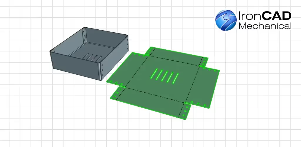

Emil Rindell

Jonas Bryntesson

Henrik Andersson
2022-05-19
Emil Rindell
Jonas Bryntesson
Henrik Andersson
2022-05-19
In this post, we'll go through how to quickly export a surface to DXF. Many times you want to be able to quickly send off a sheet of metal for laser cutting, for example - directly from the 3D scene without having to create a 2D drawing first.
We'll start with a short video describing what the tool does.
Face To DXF is a feature in ICMechanical (included for those with a support agreement) that allows you to export a surface directly from the 3D scene to DWG or DXF format. Many people use this feature on a daily basis, but few are aware of how to influence what actually ends up in the exported drawing file. Read on for an explanation!
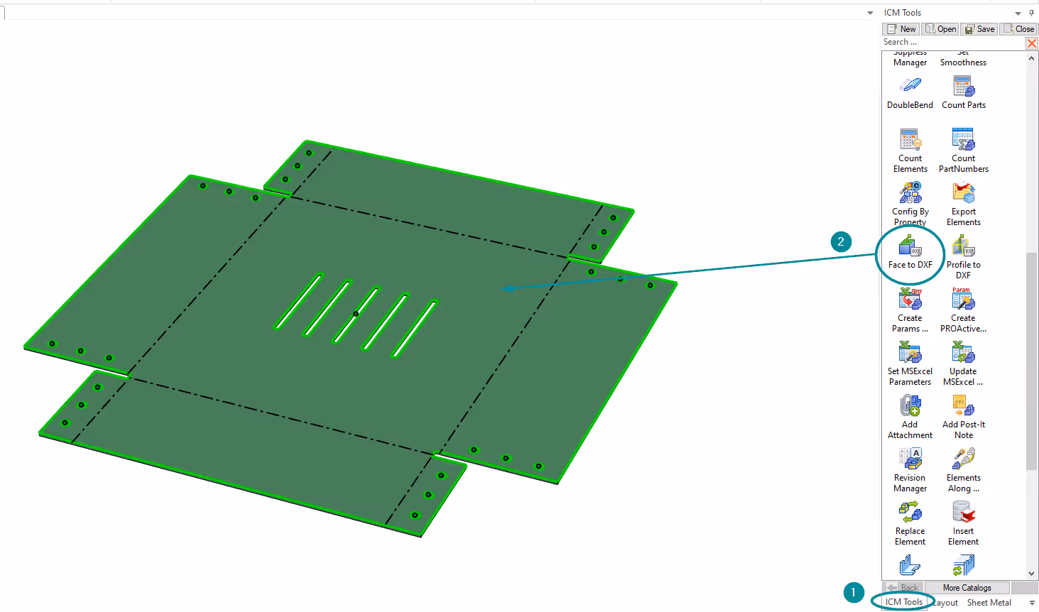
Using the Face To DXF tool is very simple. Here we show the function on an extended sheet, but you can of course use the function on other surfaces as well. Start by unfolding your plate by right-clicking on it and selecting Unfold. Then go to the ICM Tools directory, hold down the left mouse button on the Face To DXF icon and drag-and-drop the function onto the surface.
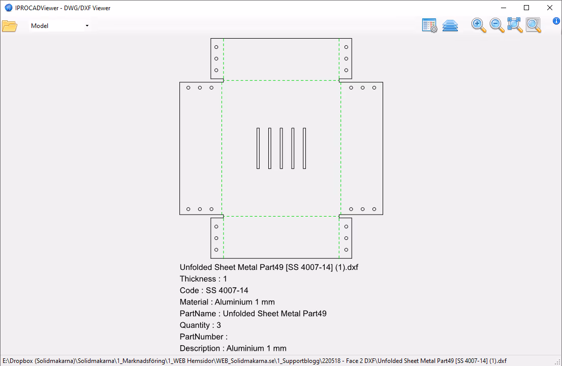
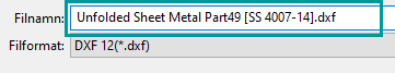
Now you will first get a dialog box where you can choose where to save the DXF file. A filename is automatically suggested, by some preset properties, but you can of course enter a filename of your choice.
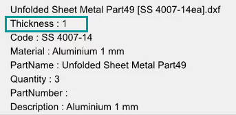
After that you will get a presentation how the DXF file looks like. The DXF file is always written in 1:1 scale and you just have to send it on for production. However, not all the information included in the drawing file may be relevant. Read on and you can see how to configure the data that is written there.
"If I have a part with subsidence or other height differences, can I still use Face To DXF?"
Of course! If you instead hold down the right mouse button and drag-and-drop the Face to DXF icon onto the surface, you'll get a tool window where you can select multiple surfaces.
Here you hold down the [Shift] key and click on the other surfaces that will follow the export. But you can also choose to select more surfaces automatically:
Select Faces on Active Part
Settings

Right-click the Face To DXF tool on a surface and go to the Settings tab(the settings can also be accessed through the Windows Start menu > IronCAD Mechanical >the IPROSettings application, Utils tab).
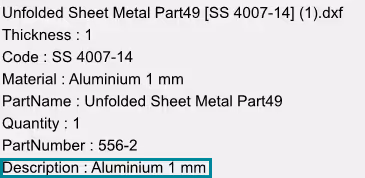
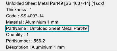
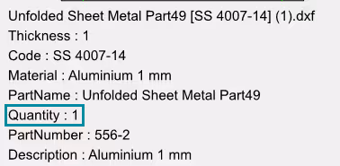
At the top, the control of the filename and how it is assembled is shown. By default, the name in the tree(Part Name) is used. But it can be a combination of Part Name, Part Number, Description and Quantity. The Separator Character menu is used to set a character that separates these values, e.g. a space, dash, underscore, etc. The value None is the default setting and does not provide a separator. NOTE! This(None) means that the last word of one value will be written together with the first word of the next value - to one and the same word. If you use more than one value, be sure to also choose a character to separate them.
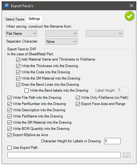
Here we find all the settings for what to write to the DXF file.
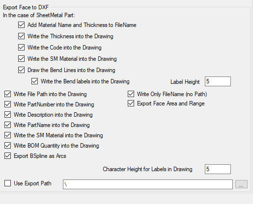

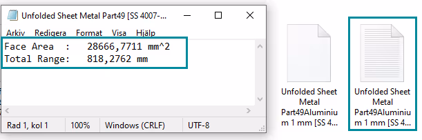
Add Material Name and Thickness to FileName - Adds the name of the material and the sheet thickness to the file name.

Write the Thickness into the Drawing - Adds the sheet thickness as a text box in the exported DXF drawing.

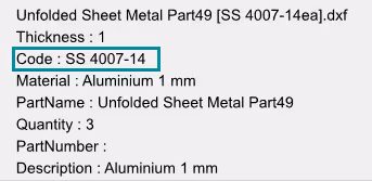
Write the Code into the Drawing - Ad ds the Material code as a text box to the exported DXF drawing.

Write the SM Material into the Drawing - Adds the name of the material as a text box in the exported DXF drawing.


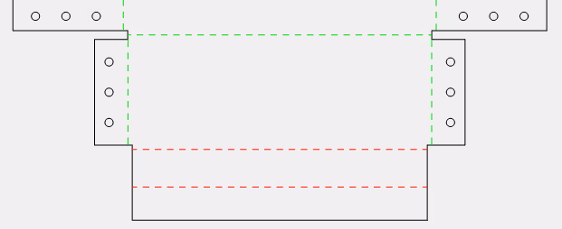
Draw the Bend Lines into the Drawing - Adds the bend lines into the DXF file (green dashed is bent upwards and red dashed is bent downwards).

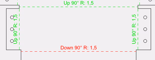
Write the Bend labels into the drawing - Adds a text showing the angle and direction of the bend where Label Height is the size of the text in mm.

Write File Path into the Drawing - Adds the path of the DXF file as a text box in the exported DXF drawing.


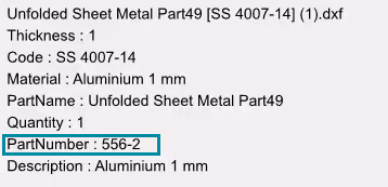
Write PartNumber into the Drawing - Adds the part number as a text box in the exported DXF drawing.

Write Description into the Drawing - Adds the description as a text box in the exported DXF drawing.

Write the PartName into the Drawing - Adds the name of the part as a text box in the exported DXF drawing.

Write BOM Quantity into the Drawing - Writes the number of parts with the same part number (Part Number) as a text box in the exported DXF drawing.

Export BSpline as Arcs - On some sheets the holes will not be perfectly round, which is correct if it is the contour of a continuous pipe at an angle to the surface. In the DXF file these holes are drawn as BSplines by default. This can sometimes cause problems in (laser/plasma/water) cutting as the processing software simply cannot read BSplines or handles them poorly. By ticking this function, which is active by default, the BSplines curves are converted to arcs instead, which all processing programs can read, but the disadvantage then instead can be that the exact shape ("the arc") is not followed.

Write Only FileName (no Path) - Writes out the file name (without the path itself) as a text box in the exported DXF drawing.


Export Face Area and Range - A text file is created in parallel with the DXF file, indicating the face area and the total perimeter of the plate.
Character Height for Labels in Drawing - Control the size in mm of the text in the text boxes in the exported DXF drawing.

Use Export Path - Here you can choose to always export all files (created by Face to DXF) to one and the same path.
Read more here:
Answer: Here we publish tips, guides, news and solutions for those who work with IRONCAD and Design Data Manager (DDM). The blog covers everything from basic functions to advanced workflows, helping you to optimize your design work. You'll find examples of smart shortcuts, practical instructions, solutions to common problems, and best practices for product design, mechanical design, and product data management.
Answer: Our guides and tips are designed for both beginners and experienced CAD users. They are aimed at designers, engineers and project managers who want to work more efficiently with IRONCAD and DDM, improve the design process, reduce mistakes and save time in product development.
Answer: We regularly publish new articles when the software is updated, when new features are introduced, or when our users ask for solutions to specific problems. The blog is therefore a reliable source for keeping up to date and getting tips that make everyday CAD work easier.
Answer: Many of our instructions and tips work in multiple versions, but we clearly indicate if an article applies to a specific version. We strive to make the content useful for older versions as well, and also provide recommendations on how to adapt workflows to the version you are using.
Answer: Absolutely! If you can't find the solution in the blog, you can contact our technical support via solidmakarna.support. Our experts will help you with everything from installation and configuration to advanced features in IRONCAD and DDM, so you can solve problems quickly and efficiently.
Answer: Yes! We appreciate suggestions from our users. If you have questions, tips or want us to address a specific issue in IRONCAD or DDM , please contact us via our contact form and we will prioritize relevant topics in future posts.
Answer: The blog contains, among other things:
Practical step-by-step guides to help you use IRONCAD and DDM more effectively.
Productivity and workflow tips for faster design and construction.
Solutions to common problems encountered by users in CAD programs.
Updates and news on new features, versions and improvements.
Best practices for data management and project organization in DDM.
Answer: All tips and guides are directly applicable in daily work. For example, you can use shortcuts and smart features in IRONCAD to speed up modeling, structure files better in Design Data Manager, or follow our step-by-step solutions for specific problems that often come up in design projects.
Answer: We strive to ensure that all guides and tips are relevant to the latest versions of IRONCAD and DDM. We also clearly mark when a post applies to an older version, so you always know if the instruction is directly applicable to your system.
Answer: Yes! Many of our users share the articles with colleagues and use them as internal training materials. The blog is a great complement to formal training and helps teams learn features faster, avoid mistakes, and standardize workflows in IRONCAD and DDM.