Looks like you don't have ESC button on your device
Download IronCAD DCS
Choose one of the following options
trial versionHas a license
Looks like you don't have ESC button on your device
Choose one of the following options
trial versionHas a license

Emil Rindell

Jonas Bryntesson

Henrik Andersson
2023-02-23
Emil Rindell
Jonas Bryntesson
Henrik Andersson
2023-02-23
How to create gears in 3D? IRONCAD is a professional 3D design tool and there are a few different tools and functions that can be used to create gears. In the video above, we go through how to use a gear generator in Draft. The generator allows you to create a 2D profile of your gear, which in turn is extruded in the Z direction to create a 3Dpart.
In the IC add-on Mechanical and the ICM Mech directory you will find the Gears tool. The gears created via ICM Gears do not use an involute curve but a circular arc/spline as an arc, which means that the gears will "lock together" if you spin them against each other. The gears created here are therefore not manufacturable, they are only schematic.
The Gears tool is also used to edit existing gears created in IC Mechanical. When you drag and drop the tool on an existing gear, the new gear is placed in the correct position.
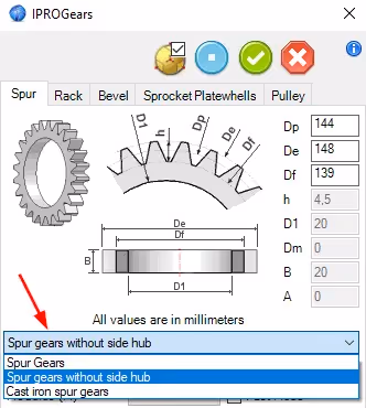
The selection of different types of gears can be found by switching between these tabs:

You can also change the type of gear by selecting the type from the drop-down menu located under the preview below each gear.

Transfer rate - This text box is available when you drop gears on an existing one and use it to define the rate.
Module - This combo box contains all values related to the module that are available.
Teeth - This box allows you to select the number of teeth.
Material - Using this combo box, the user can select the code of the material related to the component.
Fixed Mode - Select this checkbox to position a schematic component.
Authored Mode - Select this checkbox to deny access to intellishape.
The lower part of the dialog contains items that are useful for setting up information related to the component.

This is divided into two parts: BOM-info and Customized information. For a detailed explanation click here.
Each component defined in the UI has behind it some data files containing properties and parameters related to the component itself. These files are located in the default rule folder (C:\Users\Public\Documents\IronPROXT\Norme\Gears). The main files associated with the component group are the following: Main_NAME of Comp.ini and TableNAME.uni.
Each record contains the following fields:
TableName-> File containing data values that are useful for building the component
Description-> Description of the default rule
MaterialFile-> Default material allowed for this type of component
CodConf-> Configuration of code
As well as other fields specific to each component
Below is an example of the structure of a Main_Spurs.ini file
Under each section it is possible to place several entries; each entry refers to a specific rule. The files TableNAME.uni contain the fields for default values related to gear norms; the file structure is self-explanatory.
In IRONCAD under Add-Ins tab, you can press CADENAS. This is a library where there are lots of different CAD files from different suppliers.

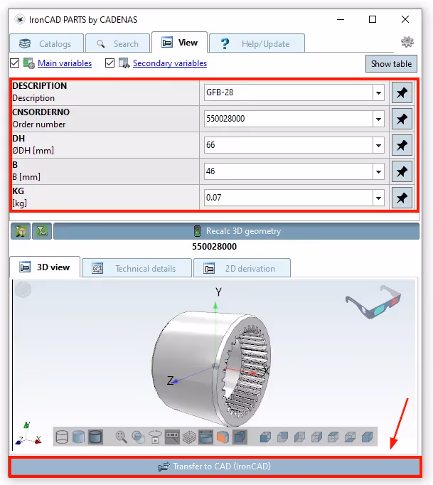
Here we can then search for what you need, in this case we just type Gears to search for some kind of gear to show the principle. Once you have found your gear, you then press Open.

Here you now have the possibility to set your parameters on the gear. When you are done, press Transfer to CAD (IronCAD)
Then fill in your details, press In acceptance... followed by Ok

Then the file will be imported to IRONCAD

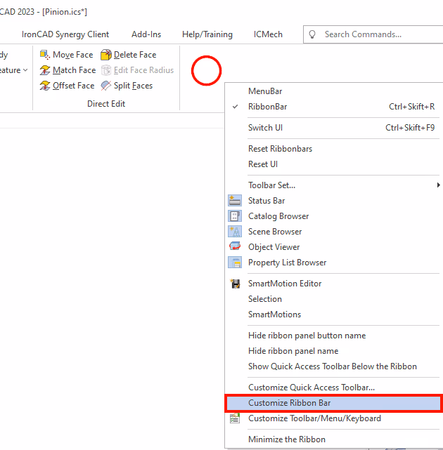
A few weeks ago we received a question to the support team on how to create a 3D pinion drive in IRONCAD. By using Structured Structured Parts in IRONCAD you can create this relatively quickly. As of version 2023, the Structured Part tab will be visible by default. If you want to do this in an earlier version than 2023, you need to manually display the Structured Part tab.
Right-click on a free field on the Ribbon Bar and select Customize Ribbon Bar
First click on a tab in the right column, then choose after which tab Structured Parts will end up, then press Structured Parts (the option will not appear to be selected) in the left column followed by Add>>

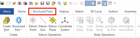
Then now comes Structured Parts will follow Home. Then close this box by clicking on the checkmark in the right corner.

Then you will see Structured Parts tab and can now follow the video above.
We would also like to promote a good website: www.geargenerator.com. It is a website that offers a tool to create and export 2D drawings of gears. The tool allows users to create gears with different number of teeth, module, angle of break and other parameters. For a small fee, the user can also choose to export the drawing in various formats such as DXF, SVG and STL.

The site is not related to IRONCAD, but serves as a tool to create gears in 2D. Once you have created your gear in 2D, you can easily extrude it in Z-direction to create a 3D model.
Answer: Here we publish tips, guides, news and solutions for those who work with IRONCAD and Design Data Manager (DDM). The blog covers everything from basic functions to advanced workflows, helping you to optimize your design work. You'll find examples of smart shortcuts, practical instructions, solutions to common problems, and best practices for product design, mechanical design, and product data management.
Answer: Our guides and tips are designed for both beginners and experienced CAD users. They are aimed at designers, engineers and project managers who want to work more efficiently with IRONCAD and DDM, improve the design process, reduce mistakes and save time in product development.
Answer: We regularly publish new articles when the software is updated, when new features are introduced, or when our users ask for solutions to specific problems. The blog is therefore a reliable source for keeping up to date and getting tips that make everyday CAD work easier.
Answer: Many of our instructions and tips work in multiple versions, but we clearly indicate if an article applies to a specific version. We strive to make the content useful for older versions as well, and also provide recommendations on how to adapt workflows to the version you are using.
Answer: Absolutely! If you can't find the solution in the blog, you can contact our technical support via solidmakarna.support. Our experts will help you with everything from installation and configuration to advanced features in IRONCAD and DDM, so you can solve problems quickly and efficiently.
Answer: Yes! We appreciate suggestions from our users. If you have questions, tips or want us to address a specific issue in IRONCAD or DDM , please contact us via our contact form and we will prioritize relevant topics in future posts.
Answer: The blog contains, among other things:
Practical step-by-step guides to help you use IRONCAD and DDM more effectively.
Productivity and workflow tips for faster design and construction.
Solutions to common problems encountered by users in CAD programs.
Updates and news on new features, versions and improvements.
Best practices for data management and project organization in DDM.
Answer: All tips and guides are directly applicable in daily work. For example, you can use shortcuts and smart features in IRONCAD to speed up modeling, structure files better in Design Data Manager, or follow our step-by-step solutions for specific problems that often come up in design projects.
Answer: We strive to ensure that all guides and tips are relevant to the latest versions of IRONCAD and DDM. We also clearly mark when a post applies to an older version, so you always know if the instruction is directly applicable to your system.
Answer: Yes! Many of our users share the articles with colleagues and use them as internal training materials. The blog is a great complement to formal training and helps teams learn features faster, avoid mistakes, and standardize workflows in IRONCAD and DDM.