Looks like you don't have ESC button on your device
Download IronCAD DCS
Choose one of the following options
trial versionHas a license
Looks like you don't have ESC button on your device
Choose one of the following options
trial versionHas a license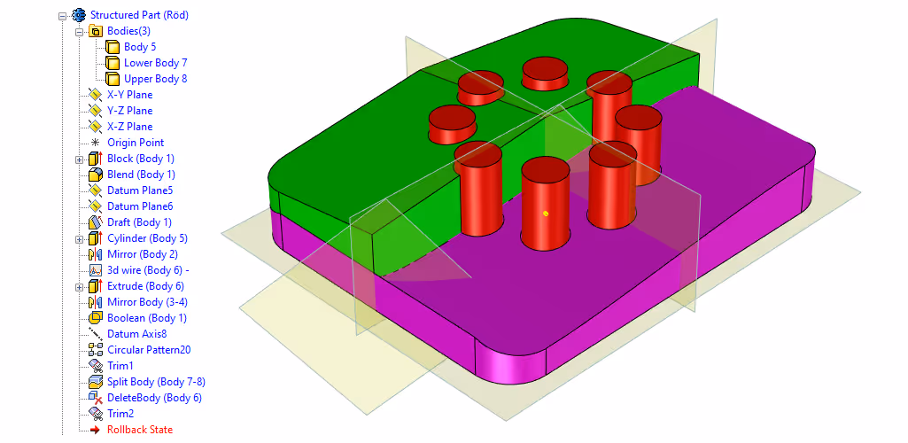

Emil Rindell

Jonas Bryntesson

Henrik Andersson
2024-03-28
Emil Rindell
Jonas Bryntesson
Henrik Andersson
2024-03-28
Following this post and the video-based exercises will give you a basic understanding of how to build and modify Structured Part parts in IRONCAD.
As you may know, there are several different types of 3D elements in IRONCAD, with Innovative Part being the most commonly used type.
Through twelve different videos that clearly show step-by-step how a part of the Structured Part type is structured and works, you can learn how to model these yourself. The exercises are entirely based on experienced IRONCAD user Malcolm Crowe's post "Structured Parts - Key Differences" on the user forum.
We will feel how to use reference planes, 3D curves and surfaces as part of the model's construction, and how different features can be associated with each other and how they in turn build individual "bodies" within the part. An important part of the exercises is to be able to handle these bodies and see when it is appropriate to use the Rollback State function to "roll back time" in the construction of the part, feature for feature.
This first overview of the Structured Part functions shows the result of the next eleven exercises and how this part is structured. The part itself is not complex or impossible to model in other ways, as will be shown in the video, but it gives a good idea of the areas that need to be mastered in order to produce such a type of part.
In order to model complex "Multi-Bodied models" in IRONCAD (which cannot be modeled with "Single-Body models" according to the Innovative Part principle), it is necessary to use the "Structured Part" modeling principle.
Areas and features such as local coordinate systems, reference planes, control and construction of Shape and Modification features, Bodies and relationships between all of these are important elements to understand the principle that Structured Part modeling follows.
What makes it unique is how the different building blocks are connected to each other and influence what happens down the part structure. A well-designed model that changes in predetermined ways can thus be updated easily and quickly. This is also known as "Design Intent". It simply limits the ways in which the model can and cannot be changed, which can also be reassuring. However, it also means that unforeseen but still necessary changes may not be possible at all and you will either have to start from scratch with a new model or hope that the model holds together even if you go backwards.
There is a special thread on the user forum where user Malcolm Crowe shows several examples of models built as Structured Parts.
An overview of how a Structured Part is built in the tree structure with its own local coordinate system. We also see that the part is a kind of "container" where we can control metadata like color. In this video we create a first part, but it is "empty" and not yet filled with any geometry or features.
A review of the structure under a Structured Part, to see the difference between a Feature and a Body. A Shape feature of type Extrude is created by dragging and dropping a Block from the Starter catalog. A Modification Feature of type Blend is added to it, following an edge in height.
Here we go into how to position shapes within a Structured Part, as TriBall and Smart Dimensions are not the primary tools. We change the setting for how a Sketch within a Shape Feature is positioned and related to the coordinate system and its origin.
Thus, we move from a "free" position control with TriBall that we are used to when modeling an Innovative Part, to a "relationship-based" position control governed by properties.
Editing the lines in the Sketch to move the corner of the rectangle to the zero point of the sketch. Next, we edit the size of the extruded block.
Adds a ten degree release angle to the top face of the model via a Modification feature of type Draft Faces that is related to a reference plane, which in turn has a relationship to another reference plane that has a relationship to three corners of the extruded Block. When the model resizes, the angled surface adapts associatively through the two reference planes.
Here we clearly learn the difference between Features and Bodies as we will mirror the previous shapes around the reference plane in the coordinate system. We merge all these new mirrored Bodies with the first one into a single Body by using a Modification Feature of type Boolean and then finish by testing the Rollback State function to "roll back time" in the structure of the part, feature for feature.
We "go back in time" and add another Shape Feature in the form of an extruded Cylinder released from the Starter catalog. Its position will be checked via associative rules against the coordinate system and the previous geometries.
A cylindrical pattern is produced from the extruded cylinder shape and as a reference for the center of the pattern we use a reference axis and we test changing the number of copies in the pattern. Then the holes for the hole pattern are trimmed via a Trim Feature.
To divide a part into two parts, you can use a surface as a dividing plane. We start by placing a 3D curve associated with the geometry and then create an extruded surface from this 3D curve. The Delete Body command creates a feature that we can easily turn on and off by suppress function or Rollback State.
The color property is primarily managed at the Part level. However, by adding color at the Surface level, we can add color to the surfaces belonging to each individual Body and thus visually separate them. We use the highlight filter command to highlight the surfaces.
It is possible to use a reference plane in the local coordinate system to trim a body. The surface created from this command uses the part color by default, but it is possible to control the color of the surfaces created in the same way as in the previous exercise 11.
If you feel you want to learn more about Structured Part, more material is available in a series of five English films at IronCAD Academy.
There are also several useful posts about Structured Part on the IronCAD user forum.
Answer: Here we publish tips, guides, news and solutions for those who work with IRONCAD and Design Data Manager (DDM). The blog covers everything from basic functions to advanced workflows, helping you to optimize your design work. You'll find examples of smart shortcuts, practical instructions, solutions to common problems, and best practices for product design, mechanical design, and product data management.
Answer: Our guides and tips are designed for both beginners and experienced CAD users. They are aimed at designers, engineers and project managers who want to work more efficiently with IRONCAD and DDM, improve the design process, reduce mistakes and save time in product development.
Answer: We regularly publish new articles when the software is updated, when new features are introduced, or when our users ask for solutions to specific problems. The blog is therefore a reliable source for keeping up to date and getting tips that make everyday CAD work easier.
Answer: Many of our instructions and tips work in multiple versions, but we clearly indicate if an article applies to a specific version. We strive to make the content useful for older versions as well, and also provide recommendations on how to adapt workflows to the version you are using.
Answer: Absolutely! If you can't find the solution in the blog, you can contact our technical support via solidmakarna.support. Our experts will help you with everything from installation and configuration to advanced features in IRONCAD and DDM, so you can solve problems quickly and efficiently.
Answer: Yes! We appreciate suggestions from our users. If you have questions, tips or want us to address a specific issue in IRONCAD or DDM , please contact us via our contact form and we will prioritize relevant topics in future posts.
Answer: The blog contains, among other things:
Practical step-by-step guides to help you use IRONCAD and DDM more effectively.
Productivity and workflow tips for faster design and construction.
Solutions to common problems encountered by users in CAD programs.
Updates and news on new features, versions and improvements.
Best practices for data management and project organization in DDM.
Answer: All tips and guides are directly applicable in daily work. For example, you can use shortcuts and smart features in IRONCAD to speed up modeling, structure files better in Design Data Manager, or follow our step-by-step solutions for specific problems that often come up in design projects.
Answer: We strive to ensure that all guides and tips are relevant to the latest versions of IRONCAD and DDM. We also clearly mark when a post applies to an older version, so you always know if the instruction is directly applicable to your system.
Answer: Yes! Many of our users share the articles with colleagues and use them as internal training materials. The blog is a great complement to formal training and helps teams learn features faster, avoid mistakes, and standardize workflows in IRONCAD and DDM.