Looks like you don't have ESC button on your device
Download IronCAD DCS
Choose one of the following options
trial versionHas a license
Looks like you don't have ESC button on your device
Choose one of the following options
trial versionHas a license

Emil Rindell

Jonas Bryntesson

Henrik Andersson
2023-05-15
Emil Rindell
Jonas Bryntesson
Henrik Andersson
2023-05-15
IRONCAD , in many ways, an incredibly versatile 3D CAD system. There are several "parallel" types of 3D objects to use, more than in most other 3D CAD systems. In IRONCAD , these are IRONCAD called 3D elements, where each type of 3D element has its own properties and functions that are optimized for creating different types of models. There are also three different methods for creating different types of parts.
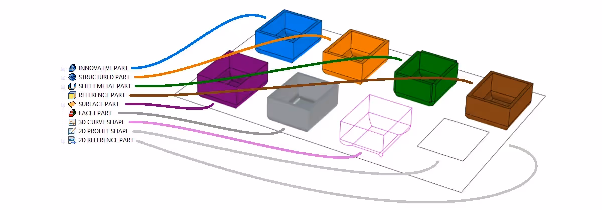
The image above shows the nine different 3D elements that can be created and managed in the 3D scene. On the left is the corresponding icon in the tree, and on the right is the model itself, which we have tried to make as similar as possible in shape. This is an attempt to clarify the differences between them, their various advantages/disadvantages, and when they are best to use.
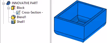
The 'normal' way of working in IRONCAD is based on the type of Innovative Part which is built and managed through a unique and dynamic history-based structure with several unique tools compared to any other 3D CAD system on the market today. This type of part is completely unique to IRONCAD. It is both feature- and history-based but despite this it does not require (and never creates any!) relations (constraints) between features.
This video shows a brief overview of the tree structure of an Innovative Part and how you can use handles to quickly and easily modify existing features in relation to other objects, without creatingconstraints. The video has no sound as this article can be read in several languages.
One of the reasons why this type of part is most often used in IRONCAD is that it is incredibly fast to model schematic models, which are always easy to change in a way that does not need to be thought out in advance. You simply change what is needed, when it is needed, in the way it is needed, without thinking at all about whether the system (predetermined rules) will allow it or not. Rarely has a tender document been completed in less time! Instead of paper and pencil, you can quickly build up a simple principle model, which you can work on immediately or at a later date.
This methodology is optimal for e.g. milled, turned or 3D printed parts that are quickly built up with a kind of advanced "primitives" by drag-and-drop technology from catalogs. These "blocks and cylinders" are for many a classic characteristic of IRONCAD, where they are called "IntelliShapes". The simplest are "partially finished" features such as an extruded "Block", which at the bottom consists of a sketch with lines. These lines can be easily and directly modified through both the round Sizebox and the angular Shape handles, which fit differently in different positions.
This video shows how to quickly throw together a simple schematic model using the drag-and-drop technique. Each feature that is added is a sketch-based extrusion, but instead of modifying it in the "classic way" via the sketch's grid, the smart handles are used to change the lines of the sketch and you can "snap" to existing geometry or write the dimension that suits the moment. The video has no sound as this article can be read in several languages.
IRONCAD's handle technique is thus primarily used to modify shapes on different types of features, which makes it easy to find graphic points to "snap to" on your own or other geometries. The handles are also usually used to modify the lines in a sketch in the fastest way possible. Since the models are quick to create, they are optimal for concept development. In principle, you never have to "start over" but continue to modify the model in various ways until it is ready.
.avif)
Imported geometry based as an Innovative Part can be modified via Direct Face Modeling(DFM) technology, where the steps and changes performed are not saved as history during the part. By "clicking down" to a green highlighted face on an imported model, it can be manipulated by activating TriBall and then moving and/or rotating the face. One or more green highlighted surfaces can also be converted to new features (so-called IntelliShapes) if necessary. These are then displayed in the tree structure under the part.
This video shows how DFM technology can be used to modify imported geometry from another CAD system in a very simple way, no matter which CAD system (as long as it is based on solid geometry) the result is the same in IRONCAD. The video has no sound as this article can be read in several languages.
Curiosity: The principle with which DFM is performed in IRONCAD was first developed by HP in Germany and the US in the late 80s and early 90s, was further developed together with the US company 3D Eye Inc. into the Windows software TriSpectives (the embryo of what later became IRONCAD) and was in the 90s also in HP's spin-off CoCreate, which was then bought by PTC and renamed to the current Creo Direct.
An Innovative Part can also contain parameterized features and sketches, partially or fully defined, if needed. This video shows how a rotated shape is modified through the parameter table, both its rotated shape and the sketch with fully defined contour lines. The video has no sound as this article can be read in several languages.
For more complicated multi-body models, however, it is necessary to use the Structured type Part, see more on this below.

In parallel with Innovative Part, in IRONCAD there is also a type of part called Structured Part. It is a type of part that the vast majority of people who use IRONCAD rarely or never encounter or even need to learn to use and can be compared to the "classic" 3D CAD structure in older parametric feature-based and "history-locked" CAD systems (also called parametric feature based modeling), with planes, bodies and having the characteristic "Rollback State" function to "go back in time".
A Structured Part does not require relationships between features to work, but works best with given conditions and rules and can also "on its own" create them in certain situations. As a rule, you should preferably plan how to build your model (what relationships features have) "in the best way" according to given conditions and rules, which is usually called Design Intent. In comparison with how an Innovative Part is built, a Structured Part usually requires much more time to figure out how the model should be built, even for relatively simple models.
This video shows what the tree structure looks like in a very simple Structured Part and how its Rollback State function works. The video has no sound as this article can be read in several languages.
You rarely modify features in a Structured Part "freely" by pulling handles, but usually by adjusting locked dimensions in sketches or via the parameter table where different features have been linked together. That said, you can of course use these smart handles here as well.
In IRONCAD Structured Part is mainly used to produce a special type of model called "multi-bodied", where the part can be likened to an assembly consisting of one or more "sub-parts" (bodies). This is mainly when modeling, for example, more advanced plastic models and molds and relatively complex parts that require a large number of features that also have a more "close relationship" to each other and therefore small changes can affect several features in predictable (planned) ways. However, this means that even with IRONCAD you can encounter so-called "Rebuild Error" which gives "broken history trees" within the part. NOTE! This only applies to Structured Part models and depends more on the principle itself than the program, which of course applies to all 3D CAD systems that similarly follow these design rules. Some people compare this technique with "programming", but then of 3D geometry and you usually need to keep notes on how the model is supposed to work in case of future changes.
There is an interesting Thread On IronCAD's user forum where users view examples of Structured Parts.
Imported geometry based as a Structured Part can also be modified via Direct Face Modeling(DFM) technology, where every step and change made is saved as editable "events" in the history (tree structure) of the part. The video shows how this is done, which is different from an Innovative Part that does not save the corresponding changes within the part in the same way at all. For a small number of changes, it can sometimes be an advantage that these DFM events are saved within the part, but more often than not, there is no advantage in saving every moment/change and it can also have negative side effects as certain types of changes can contradict each other and prevent a certain change from being executed at all. The video has no sound as this article can be read in several languages.
Read more and learn how to use Structured Part in IRONCAD through the guide on our Support Blog.

For cut and folded sheet metal or cut and folded corrugated cardboard, which can be unfolded if necessary, the Sheet Metal Part type is preferred. It is based on a partially different type of tree structure under the part itself compared to the two previous types (a kind of intermediate between the two) and has a slightly different order of features compared to them. Many of its properties are also completely table-driven, such as thickness, material, bending radius, bending angle and k-factor.
When a Sheet Metal Part is unfolded, a new part is created in the tree, named "Unfolded... ", containing a Boundary Representation model(a topologically defined geometric shape) and sometimes negative "tool features". This unfolded part is not intended to be modified, but is mainly used for export to a cutting format which is usually *.dxf.
This video shows a brief overview of a Sheet Metal Part, its tree structure and how to unfold it and manage the parallel unfolded part. The video has no audio as this article can be read in several languages.
Once modifications have been made to the bent plate, make sure to update the unfolded variant via the Unfold option on the part's right-click menu. The unfolded part also appears in a separate configuration that can be depicted on the 2D drawing.
There are also tools to convert selected surfaces from other parts or imported BRep models to a new Sheet Metal Part via the Sheet Metal ribbon tab in IRONCAD. The thickness can be read from the selected model or picked from the sheet metal table.
There are plans to implement some DFM functions also on a Sheet Metal Part, e.g. to extend a sheet by first marking a surface and moving it with the TriBall. This would be useful e.g. on corrugated board models that use the Sketched Bend function for multiple consecutive folded edges. But currently it is not possible to modify a Sheet Metal Part with these functions.

As an option for imported 3D geometry, there is the Reference Part which is used when you do not want it to be possible to change it, either intentionally or by accident. The tree structure of the part cannot be expanded, as it has no features that can be modified. If you try to add new features to it, e.g. by dropping shapes from a catalog, a message is displayed that this is not possible. As the name reveals, the main use is as a reference, which other geometries can take into account or perhaps purely visual to show a customer product in relation to your own product.
However, if necessary, it can be "switched over" to become an Innovative Part and modified with DFM technology and get more features "in the usual way". This video shows that it is not possible to edit a Reference Part and how to easily convert it to an Innovative Part to add more features. The video has no sound as this article can be read in several languages.

A surface model in IRONCAD is called Surface Part. It can be built up from 3D curves and 2D sketches in IRONCAD, or created by imported models but without controllable features (3D curves or 2D sketches). Surfaces are sometimes used to cut solid models (as a kind of negative feature, through a Boolean operation) and can be included as a feature in both an Innovative Part and a Structured Part, where in the latter it is also managed as a stand-alone "Body".
It is relatively common that e.g. an imported *.step file comes in as a large number of surfaces, which can affect the performance of the 3D scene. However, there are some settings under Import Options to review that can merge most or all surfaces into a single surface model. In some cases, if the surface model proves to be "watertight", IRONCAD itself can convert it to a solid BRep shape, allowing it to be edited using DFM technology or adding new features.
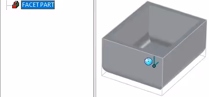
Importing a facet model creates a facet Part which usually enters IRONCAD through the file formats *.stl, *.obj, *.skp or (3D) *.dxf. They lack information about volume and in order to be modified at all, they must first be converted to an Innovative Part which then consists of a topologically defined solid geometry (BRep-feature), which if necessary can also be linked as a stand-alone"Body" in a Structured Part. The modification of such a BRep-feature is, as previously mentioned, done with DFM technology.
A Facet Part is mainly used as a reference geometry in 3D space.
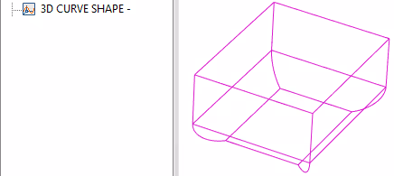
A 3D geometric line/curve in the 3D scene is called a 3D Curve Shape. It can be used as a reference line for swept or lofted shapes or surface models in an Innovative Part or just as it is to e.g. correspond to the centerline of a hose or wire. It can also be used as an input feature or created from (and simultaneously associative with) one or more geometric edges from a feature in a Structured Part.
They are most easily created using the 3D Curve tools, either by left clicking on known geometric points or by using TriBall to position each point of the 3D curve in XYZ space. You can also "click down" and green-mark a surface or edge on an existing part and from there "extract" a 3D curve(Extract 3D Curve).
The length of a 3D curve is displayed under Part Properties and can also be read out as a property from a swept shape.
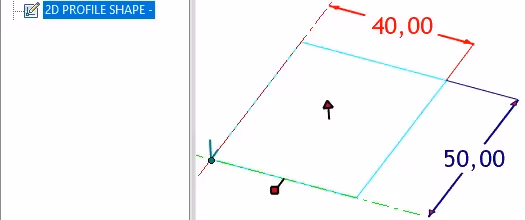
To put lines on a plane, a 2D Profile Shape is first created. This plane with lines (generally in CAD called a "sketch") is usually part of a feature in an Innovative Part or used as an input feature in a Structured Part. But it can also be its own stand-alone 3D element where the 2D lines are used as reference lines or as a base for creating new geometries in other parts. The lines can be modified either by working with the sketch in the plane where they were first created, or via handles where you can easily set measurements against other geometries.
You can import 2D geometry from *.dwg, *.dxf and *.exb files, or copy and paste lines from the (2D CAD) CAXA DRAFT environment in IRONCAD.
You can also apply "locked" or "open" Smart Dimensions to the lines in the sketch. If they are locked, it corresponds to them being managed by constraints (with a red color) and can then also be checked and linked via the parameter table. If Smart Dimensions are instead "open" (with a blue color), you can quickly get an overview of which dimensions are available and they can still be edited when needed, but they cannot be controlled or linked via the parameter table.
In the picture above, we see both variants of locked (red) and open (blue) dimensions and a profile handle at the bottom left. The handle shown in the center of the profile itself can be used to quickly and directly extrude a selected 2D Profile Shape into a new Innovative Part.
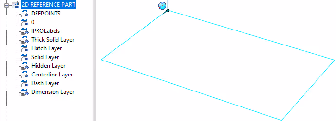
By creating a 2D Reference Part you can import a kind of "lightweight version" of 2D drawings in *.dwg or *.dxf file format that is not primarily used to create 3D geometries. When importing large sites where a reference plane with lines is required, this type of part is optimal. In this way, you can quickly place finished parts or assemblies, e.g. by pulling them out of a catalog and "snapping" to lines and points that light up in a green color, as shown in the video below. The video has no sound as this article can be read in several languages.
All layers are displayed as "features" under the part and can be individually turned off and on.
It is also possible to project contour lines from this 2D Reference Part to a 2D Shape (sketch) which in turn is used to create a feature in an Innovative Part, a Structured Part or a Sheet Metal Part.
Answer: Here we publish tips, guides, news and solutions for those who work with IRONCAD and Design Data Manager (DDM). The blog covers everything from basic functions to advanced workflows, helping you to optimize your design work. You'll find examples of smart shortcuts, practical instructions, solutions to common problems, and best practices for product design, mechanical design, and product data management.
Answer: Our guides and tips are designed for both beginners and experienced CAD users. They are aimed at designers, engineers and project managers who want to work more efficiently with IRONCAD and DDM, improve the design process, reduce mistakes and save time in product development.
Answer: We regularly publish new articles when the software is updated, when new features are introduced, or when our users ask for solutions to specific problems. The blog is therefore a reliable source for keeping up to date and getting tips that make everyday CAD work easier.
Answer: Many of our instructions and tips work in multiple versions, but we clearly indicate if an article applies to a specific version. We strive to make the content useful for older versions as well, and also provide recommendations on how to adapt workflows to the version you are using.
Answer: Absolutely! If you can't find the solution in the blog, you can contact our technical support via solidmakarna.support. Our experts will help you with everything from installation and configuration to advanced features in IRONCAD and DDM, so you can solve problems quickly and efficiently.
Answer: Yes! We appreciate suggestions from our users. If you have questions, tips or want us to address a specific issue in IRONCAD or DDM , please contact us via our contact form and we will prioritize relevant topics in future posts.
Answer: The blog contains, among other things:
Practical step-by-step guides to help you use IRONCAD and DDM more effectively.
Productivity and workflow tips for faster design and construction.
Solutions to common problems encountered by users in CAD programs.
Updates and news on new features, versions and improvements.
Best practices for data management and project organization in DDM.
Answer: All tips and guides are directly applicable in daily work. For example, you can use shortcuts and smart features in IRONCAD to speed up modeling, structure files better in Design Data Manager, or follow our step-by-step solutions for specific problems that often come up in design projects.
Answer: We strive to ensure that all guides and tips are relevant to the latest versions of IRONCAD and DDM. We also clearly mark when a post applies to an older version, so you always know if the instruction is directly applicable to your system.
Answer: Yes! Many of our users share the articles with colleagues and use them as internal training materials. The blog is a great complement to formal training and helps teams learn features faster, avoid mistakes, and standardize workflows in IRONCAD and DDM.