Looks like you don't have ESC button on your device
Download IronCAD DCS
Choose one of the following options
trial versionHas a license
Looks like you don't have ESC button on your device
Choose one of the following options
trial versionHas a license

Emil Rindell

Jonas Bryntesson

Henrik Andersson
2025-02-18
Emil Rindell
Jonas Bryntesson
Henrik Andersson
2025-02-18
We are sometimes asked how best to create a compact (simplified) part a whole assembly.
The area of use can be different, but it is usually a question of wanting to share "just enough" of your construction with someone else. It can also be a matter of a larger layout where you want simplified versions of machines, conveyors and other equipment.
Disadvantages of a single part
Itmay be good to mention that there are also disadvantages in terms of performance of merging many parts into a larger part that then consists of more surfaces and edges because it gives a more complex topology = more "concentrated data" = more for the processor / solid core to calculate. See details about this further down.
This can usually be divided into three steps that can be run in different combinations or all together -> 1) Manual removal - 2) Merge parts - 3) Simplify parts.
Please takea few minutes to go through the tree structure of the file and remove the most obvious parts and assemblies that absolutely must not be shared with third part.
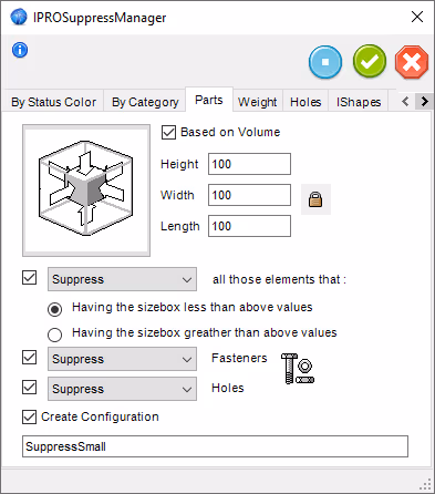
Suppress Manager (IC Mechanical)
Withthe addition IronCAD Mechanical there is a smart tool Suppress Manager that cansuppress (Suppress) or delete(Delete) objects or features based on various properties such as size, color and several other things.
Removing anything smaller than a certain dimension, say anything that fits within a cubic decimeter, usually clears the 3D scene of lots of unnecessary details such as screws, washers, nuts and other small standard components that are not visible or have any function in a layout drawing anyway. If the fasteners and threaded holes are created via the IC Mech tools, you can also ensure that these are included when the command is executed.
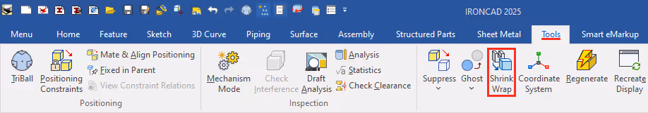
Remove via Shrink Wrap
Anotheroption is to use the Shrink Wrap (see also step 3) todiscard parts.

Youcan combine multiple parts into one by running the Boolean Union command found under the Feature. This follows the classic 3D CAD function of combining multiple geometries into one. Start the tool and select the parts to be joined. You can also start by selecting the parts and then run the tool.
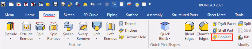
NOTE! Be aware that the tree structure may prevent some parts from being merged. These must be under the same assembly for the system to accept the execution of the command.
It is worth noting that this function(Boolean) is automatically executed every time you drop a feature from a catalog onto an existing part in the 3D scene. Take for example an H Block that automatically cuts away material from the part it is dropped on. Something that makes IRONCAD very easy to use, without even thinking about it!
Maybe there needs to be a "replacement part" in the same place. The easiest way to solve this is to create a new part by releasing a new Block or Cylinder from a catalog and changing it to "approximately the right size".
The next level is to keep the part, but manuallysuppress ordelete the features that do not need to be visible. You can keep several of the features that build a part but remove all negative features.
Combine Shapes
In addition, with the Combine Shapes command, all features under a part can be combined into a single feature feature. Select certain features to combine them only, but keep the rest of the part structure.

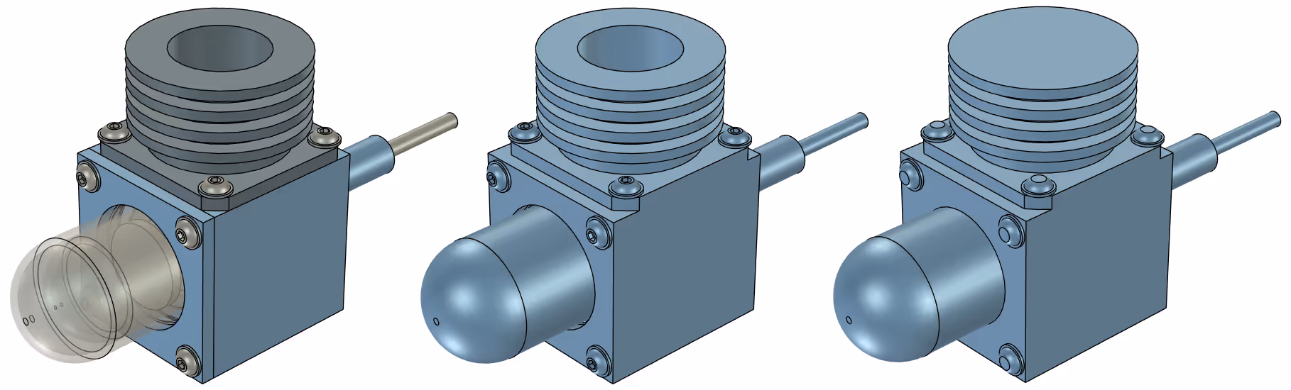
The Shrink Wrap tool
Shrink Wrap is a quick and easy way to simplify solid geometries by sealing all voids. Actually, the tool should perhaps instead be called Simplify Solid, because it does not create a "shrink wrap" in the true sense of the word (ie as a "sheet" tightly vacuum-packed around the geometry) but it is simply a "simplified solid" with as few surfaces / edges as possible that are created.
There are several uses and options for Shrink Wrap, but in this post we focus on simplifying an Assembly. Here is a video from IronCAD Academy Commands.
Cubify via Shrink Wrap
Another option isto use the Shrink Wrap (step 3) to "cubify" one or more selected parts, so that they are radically simplified instead of disappearing completely.
Activate Convert Part To Block and simply select the parts to be "cubified".

*BRep = Boundary Representation
This isa topological (mathematical) definition of a solid model in a 3D CAD system. In many 3D CAD systems, these models are called "dead", which means that it is not possible to modify the geometry of the imported model. It is often necessary to run commands that read and convert geometries in models to features, something that is usually calledFeature Recognition" and which does not always work perfectly.
NOTE! With IRONCAD you can use the Direct Face Modeling tools and easily modify the shape of even imported solids by quickly and directly dragging their faces, moving the faces with TriBall or right-clicking and removing voids. In this way, IRONCAD is also included among 3D CAD systems defined as "direct editors", but is not limited to that alone. There are also sketches, story trees with features and parametric table control as well as constraints and kinematic movements.
**Disadvantages of "one part of everything" compared to several simpler parts
Animportant thing to keep in mind about 3D CAD in general and "solid geometry" in particular is that the more number of faces, edges and points (face, edge, vertex - the topological data that builds the model) that a solid 3D CAD model consists of - the larger the file size and computing power it requires to be saved or modified.
The amount of data affects the time it takes to load or save a file, but it also affects graphics performance and how quickly you can click and select an object. A sphere has 1 single surface and at the same time 0 edges or points, possibly 1 center point in the middle of the sphere - it doesn't get any simpler and less data than that on a solid geometry.
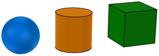
A cylinder in turn has 3 surfaces (2 flat circular surfaces and 1 cylindrical mantle surface in between) with 2 circular borders on each side and having 4 quadrants on each circle.
A cube has 6 flat faces with 8 edges around them. This in turn gives 8 intersection points at the corners and also 8 center points on the edge lines. Already here we have a multiple increase in the amount of data on three very simple objects.
If you think of an entire machine structure as a single part, that would probably mean many thousands of surfaces and edges. In that case, it might actually be better to have a lot of parts, but that each part is very "simple" instead = that each part has as few surfaces and edges as possible.
Other options?
Alternatives to "solid" geometry can instead be "facet data" or "surfaces". These do not require as much data for a representation model similar to a solid model, but both lack, for example, the ability to read out volume or weight. Facet models also lack "roundness" in the form of circles, arcs and radii.
Answer: Here we publish tips, guides, news and solutions for those who work with IRONCAD and Design Data Manager (DDM). The blog covers everything from basic functions to advanced workflows, helping you to optimize your design work. You'll find examples of smart shortcuts, practical instructions, solutions to common problems, and best practices for product design, mechanical design, and product data management.
Answer: Our guides and tips are designed for both beginners and experienced CAD users. They are aimed at designers, engineers and project managers who want to work more efficiently with IRONCAD and DDM, improve the design process, reduce mistakes and save time in product development.
Answer: We regularly publish new articles when the software is updated, when new features are introduced, or when our users ask for solutions to specific problems. The blog is therefore a reliable source for keeping up to date and getting tips that make everyday CAD work easier.
Answer: Many of our instructions and tips work in multiple versions, but we clearly indicate if an article applies to a specific version. We strive to make the content useful for older versions as well, and also provide recommendations on how to adapt workflows to the version you are using.
Answer: Absolutely! If you can't find the solution in the blog, you can contact our technical support via solidmakarna.support. Our experts will help you with everything from installation and configuration to advanced features in IRONCAD and DDM, so you can solve problems quickly and efficiently.
Answer: Yes! We appreciate suggestions from our users. If you have questions, tips or want us to address a specific issue in IRONCAD or DDM , please contact us via our contact form and we will prioritize relevant topics in future posts.
Answer: The blog contains, among other things:
Practical step-by-step guides to help you use IRONCAD and DDM more effectively.
Productivity and workflow tips for faster design and construction.
Solutions to common problems encountered by users in CAD programs.
Updates and news on new features, versions and improvements.
Best practices for data management and project organization in DDM.
Answer: All tips and guides are directly applicable in daily work. For example, you can use shortcuts and smart features in IRONCAD to speed up modeling, structure files better in Design Data Manager, or follow our step-by-step solutions for specific problems that often come up in design projects.
Answer: We strive to ensure that all guides and tips are relevant to the latest versions of IRONCAD and DDM. We also clearly mark when a post applies to an older version, so you always know if the instruction is directly applicable to your system.
Answer: Yes! Many of our users share the articles with colleagues and use them as internal training materials. The blog is a great complement to formal training and helps teams learn features faster, avoid mistakes, and standardize workflows in IRONCAD and DDM.