Looks like you don't have ESC button on your device
Download IronCAD DCS
Choose one of the following options
trial versionHas a license
Looks like you don't have ESC button on your device
Choose one of the following options
trial versionHas a license

Emil Rindell

Jonas Bryntesson

Henrik Andersson
2024-04-25
Emil Rindell
Jonas Bryntesson
Henrik Andersson
2024-04-25
Something else unique about IRONCAD is the principle with which you work in the sketch. That is, the plane, sometimes also called the "grid" or "Cross-Section", where you draw the lines that are the basis for different shapes such as an Extrude, which is one of four so-called Shape Features. But the sketch is also used by some Modificationfeatures such as Rib and Emboss etc.
The sketch in IRONCAD does not require "fully defined rules" through constraints to give you full control and precision, as there are several unique tools and some basic rules and features that we will look at in this blog post.
As you have probably heard or read before, there are many different ways to work in IRONCAD and some people choose (actually!) to never learn how to use the sketch."You don't have to!". For those who think it works well enough to quickly use "ready-made" 3D models from catalogs and easily handle them with handles - every thought of having to use the sketch can make them shudder!
For more experienced users, the sketch may be a necessity depending on the look and feel of the model, but it's not always easy to get the hang of how it really works in a way that feels "fluid". However, it's quite striking how easy the tools you need to use actually are if you give them a chance.
To create a solid shape via e.g. an Extrude Shape-feature , only a number of lines are required, which together form a closed contour. This can then be modified in a variety of ways, which may be suitable depending on when and where you are in the process, and of course what tools you know and master.
Before we start - the sketch as a (2D) CAD tool...
If you are an experienced 2D CAD (read: AutoCAD) user, several basic steps, commands and tools differ from how they are used there. This means, of course, that you may experience certain steps as backwards or unclear. This is often the case when switching between different CAD/CAM systems. But remember that the sketch is the basis for a 3D geometry and with IRONCAD you should spend as little time as possible having to use the sketch to change the shape and location of the lines that are there.
...and the sketch in comparison with other 3D CAD systems.
If you have been using another 3D CAD system based on the well-known and widely used Parametric Feature based principle, you are usually used to spending a lot of your time in the (2D) sketch and also usually "defining" it with various rules and limitations, also called constraints. In some cases, you cannot proceed without "fully defining" the sketch - > so that it is not possible to change its shape in any way with "some kind of unknown and uncontrolled freedom".
These types of rules primarily do not need to be applied in IRONCAD, mainly because there is no "unknown or uncontrolled form of freedom" of the kind one might be used to from other CAD systems. Instead, one usually prefers to avoid constraints altogether, but one can still have full control over the vast majority of ways to modify the lines that are there. Something that to many may at first seem extremely strange or sound completely unrealistic.
However, this is possible because IRONCAD has a number of unique smart tools and convenient commands tied directly to the 3D models, e.g. one usually prefers to change the lines through handles instead of "going back" and editing the sketch. It is of course possible to use constraints and "fully defined" sketches also in IRONCAD, but you usually only do it when it is actually needed and it makes a clear difference.
All operations described below actually deal with "a point in an XY coordinate system". Each step performed will add or move one or more points in the XY plane, resulting in the creation, reshaping or moving of lines. If you know that this is the basis of the sketch in IRONCAD, then you may find it easier to see and understand the principle behind the tools and the options available.
Sketch 1a -Two Point Lines
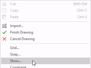
A simple overview of the Two Point Line command set between two points (XY coordinates) in the sketch in IRONCAD. Note the difference between the right and left mouse button, with the right (always) providing more options.
Sketch 1b - Polyline
A simple overview of the Polyline command, which is set between two points (XY coordinates) in the sketch in IRONCAD, but where you can continue with another line directly after the previous one. You can also easily switch to an arc of a circle. Note the difference between the right and left mouse button, with the right (always) giving more options. End a line by double-clicking with the left mouse button or end the command with [Esc].
Sketch 1c - Rectangle
A simple overview of the Rectangle command set between two points (XY coordinates) between two corners in the sketch in IRONCAD. Consider the difference between the right and left mouse button, with the right (always) providing more options.
Sketch 1d - Circle
A simple overview of the Circle command set between two points (XY coordinates) for the center and radius of the sketch in IRONCAD. Note the difference between the right and left mouse button, with the right (always) providing more options.
Sketch 1e - Endpoints in the Sketch
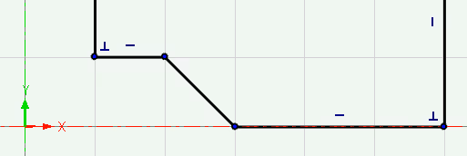
The sketch consists of lines that are controlled by the end points at which each line begins and ends. You work with points in an XY coordinate system that control the length and position of lines. The endpoints can be moved "freely" by dragging them with the mouse cursor, or with different types of "control" based on what you have selected.
By selecting one or more lines, you temporarily constraint what can and cannot be changed. This is a big difference compared to placing permanent constraints! A selected line will follow other lines that change shape.
Sketch 2 - Selection, an important control in Sketch
Selecting objects in the sketch is a simple but important way to gain more control. Selected lines will move when another line changes length. Keep in mind that it is always the endpoints of the lines that move when you move or change the length of the lines!
When a line is extended, the connecting line will be affected and will have to change its shape or move. But how can you predict what will happen, before making the change and without using constraints? Remember that it is always the endpoints of the lines that are moved when you move or change the length of the lines!
Sketch 3a - Selection controls change of direction in the Sketch
Depending on which side of a line you select, you control the length in that particular direction. Remember that it is always the end points of the lines that are moved when you move or change the length of the lines!
Sketch 3b - Changing the length of lines and managing Maintain End Conditons.
When a line changes length (end point is moved), you can control how connecting lines are affected, whether they are moved with and maintain their angles or whether they change their length and angle. This is controlled by the Maintain End Conditions setting. This property is only displayed when editing the "curve dimension" of a line and is (unfortunately still) not possible to control via the Property Browser, where this property is always "off".
If you don't know this, you can easily feel that the sketch lacks precision and control.
Sketch 3c - More control over length and angle with the Curve Dimension handles.
By default, when a line or circle is selected, a dimension is displayed through the Curve Dimension function, which allows you to change the length, angle and radius. This feature also has smart handles so you don't have to know exactly what dimensions you're looking for. Just like the handles on Shape features, you can drag and snap to other geometries!
When one or more lines are moved, the connecting line(s) will be affected and will be forced to change their shape or to move (the end points are moved). How can you predict what will happen, before making the change and without using constraints? Depending on the commands used or if you combine with different keyboard shortcuts, you can get full control over this. There is also the SmartSnap function that appears as a green dot and helps you find other geometries to snap to.
Sketch4a - Move command on lines connected to other lines
When using the Move command, it is useful to know how connecting lines behave, depending on whether they are selected or not. This is especially true for lines that are not connected perpendicularly but at an oblique angle. Remember that it is always the endpoints of the lines that are moved when you move or change the length of the lines!
Sketch4b - Moving lines and using SmartSnap
When selecting and drawing a line with the left mouse button, the nearest end point will use the SmartSnap function, which appears as a green dot and shows where the line being drawn will end up. For example, the "nearest corner" of a simple rectangle. You can also use this to find intersections between angled lines and 3D geometries.
Sketch4c - Unlock temporary relations with [Shift].
When drawing a line, you can temporarily unlock temporary relations with other lines by holding down the [Shift] key while moving the line with the mouse pointer. The precision then lies in the fact that SmartSnap can snap to the end point closest to the mouse pointer where the line is drawn. The connected lines must adapt their length and angle to solve this. This is also shown in point 10b Chamfer.
Sketch 4d - Temporarily lock along the XY coordinates with [Alt].
When dragging an endpoint or lines, you can hold down the [Alt] key to lock to the XY axes.
-video
IronCAD was early to develop a feature for the sketch called SmartCursor, which means that the mouse pointer and the selected object work together to find interesting information in its vicinity. This is shown by green dashed lines appearing around the cursor, e.g. when dragging an endpoint or a line.
If there is too much information, you can temporarily turn off the SmartCursor function by holding down [Shift]. However, you can still use the SmartSnap function to snap to other lines or to the grid in the sketch. SmartSnap appears as a green dot near the mouse pointer.
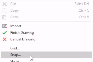
If you don't want to use the SmartCursor at all, you can permanently disable it in the Snap settings. In this case, the green dashed help lines will no longer appear in the sketch.

Something that IRONCAD has done very well since its inception is to allow the user to modify the lines in a sketch through visual easy-to-use handles that appear in the "regular 3D modeling mode". These handles are called Shape handles and usually appear at the corresponding mid point of each line, but only when the mouse pointer is near that particular line. For circles, the handles appear on a quadrant and control the radius of the circle, but you cannot move a circle using any handle.
Sketch 6a - Use the Shape handles to modify the lines in the Sketch.
Instead of "going back" to Sketch to make changes like moving lines, you can use the smart and easy-to-use Shape handles that appear on each line.
Sketch 6b - Associating a Shape handle with a geometric edge
On the right-click menu of a Shape handle is the Associate to Edge option. This creates a permanent lock through a Project Constraint in the sketch. You can no longer access the menu for the handle, as the edge/line is now associated to another edge. By editing the sketch, you can reach the constraint and remove it, if you want.
NOTE! Keep in mind that you cannot visually see this association/constraint once it has been applied, even though it is there. The constraint is only visible in the sketch.
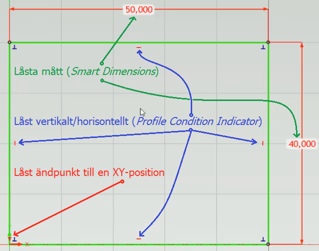
Instead of using red and locked dimensions(Smart Dimensions) that do not allow you to change the length or position of lines in any other way, you can unlock them -> but they still have an interesting function. Instead, they act as a unique combination of "reading and controlling dimensions" (also called Reference Dimensions) and you can directly see the length of a line or the distance between lines.
These dimensions are shown in a dark blue color instead of the red (locked) color. It is still possible to change a dark blue dimension and if you double click on one of the dimension arrows you can control the direction of the change.
To "unlock" a red Smart Dimension, right-click and uncheck Lock in the menu. The color will turn blue and the dimension text will update in real time if the point or line is moved with the mouse cursor or a Shape handle.
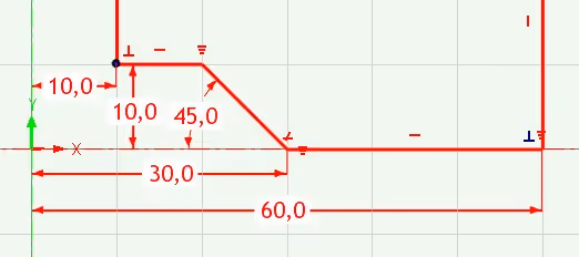
Sketch 7 - Unlocked (blue) Smart Dimensions
Here is an example of combining the freedom of Shape handles with lines managed via red locked Smart Dimensions (Constraint Dimensions) or with blue unlocked Smart Dimensions (Reference Dimensions) and why this is a useful and flexible combination.
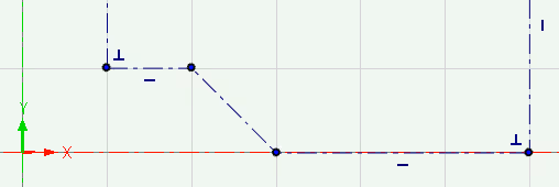
There is something in the sketch called Profile Condition Indicators, which are small blue symbols that can appear next to certain lines and show the "temporary relationship" of the line to the Sketch's XY coordinate system or to other lines.
This is not a lock in the form of a constraint but first and foremost "an indicator of how the line is currently oriented in the sketch or towards other lines". However, you can easily lock such an indicator to become a constraint by double-clicking or via the right-click menu on the indicator itself.
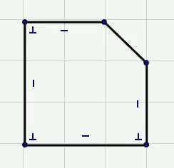
These blue indicators appear "at the center" of lines that are "parallel to the XY coordinate system" and "at the corners" of lines that have a "perpendicular relationship" to each other.
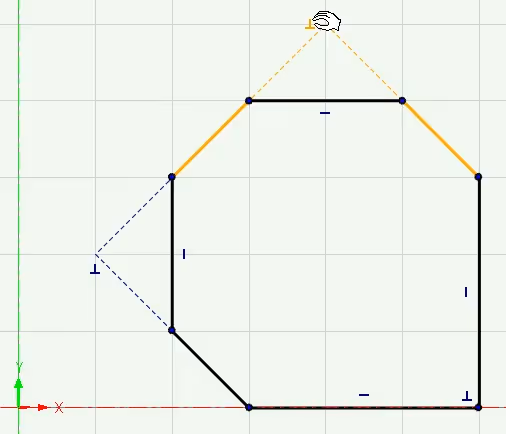
It can also be displayed as blue dashed lines with an indicator to show the temporary relationship between lines that are not directly connected to each other. By placing the mouse cursor on an indicator, an orange color shows which lines are indicated to have a temporary (blue indicator) or permanent (red indicator) relationship with each other.

They also appear between lines, circles or arcs that have "smooth" tangent relation. When locked as a constraint, they are shown in red, which we'll look at later. By placing the mouse cursor on an indicator, an orange color shows which lines are indicated to have a temporary (blue indicator) or permanent (red indicator) relationship with each other.
Under the sketch's Snap settings(right click in the background), you can control the types of indicators to be displayed in the sketch.

Although it is generally not recommended to use constraints in the Sketch in IRONCAD, unless you are absolutely sure that you really need it or want to parameterize lines in the sketch, there are some occasions where some types of constraints can be useful and give a little more control under certain conditions.
Sketch 9a - Tangent constraint
It can be difficult to "freely" draw endpoints and lines when there are arcs connected. Without a "smooth" tangent transition you get an ugly "crease". This Tangent relation is shown by an indicator that can also be locked as a constraint.
Sketch 9b - Horizontal and Vertical constraints
Locking a line parallel to the X or Y coordinates ensures that the lines can only follow parallel to the coordinate system. This avoids unwanted angles on "straight lines". But it can also cause problems, as it is not possible to angle a line and other lines are then "pushed away" for a long distance.
Sketch 9c - Project constraint
Projecting contours from other 3D models while creating a locked relationship with the geometry. If the other geometry changes shape, it will immediately change the shape of the projected lines in the sketch.
Sketch 10a - Fillet (radius) with and without constraints
The Fillet command places radii as a kind of "feature", with or without constraints, between lines. Note the difference between the right and left mouse button.
Sketch 10b - Chamfers with and without Constraints
If you need a chamfer between two lines, you can use the Chamfer command. It has several measure-driven variants where you can also choose to add locked dimensions as constraints. This video goes through the different variants and compares the difference between them. Keep in mind that it is usually an advantage to add a chamfer as a Modification feature, so you can more easily reach it to change or suppress. Having simpler shapes in the sketch also makes the handles easier to use and gives more predictable results.
Sketch 10c - Mirror with Constraint
When mirroring lines in the sketch with the Mirror command, you can choose to simultaneously create a constrained relation between the lines that are mirrored. However, there is no difference between the lines in terms of"Master/Slave", which makes it easy to change whichever side of the lines you need to change.
Sketch 10d - Offset with Constraints
The Offset command allows you to set a locked measure that controls the copied lines, which are also accessed outside the sketch.
We have produced a video showing how to check all the dimensions of a long rounded crank. This is a shape that cannot otherwise be adjusted in a predictable way with either handles or any kind of "freedom" in the sketch. Here locked dimensions and relationships provide a fully predictable model.
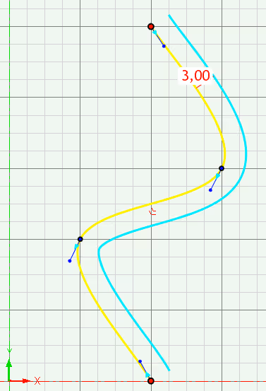
Splines can be controlled via the insertion points along the spline curve. Each point can be controlled by measurements.
-video
The lines in the sketch can be displayed in several different colors but the most common color of lines is black (formerly white). However, it is good to know when and why certain lines are sometimes shown in a different color!
Under Defined -> Black
Black (formerly white) thick lines are called Under Defined and represent the default mode in the sketch in IRONCAD. Since they are not managed by locked relations and constraints, you can make very many types of changes with them, sometimes even "illogical" -> remember that it is the endpoints that govern and the lines on each side of the endpoint must adapt accordingly! This is also the reason why they are handled as Under Defined by the system, they lack "enough" constraints to be handled e.g. by a parameter table and can therefore easily be changed by handles "outside" the sketch.
Keep in mind that Under Defined never means "without control" in IRONCAD.
This is an amazing strength and flexibility that opens up with IRONCAD and something that is absolutely beneficial to learn, there is no equivalent way to modify lines in the sketch with any other 3D CAD system on the market today.
FullyDefined -> Green

Green thick lines mean that the lines are "fully defined" and can only be changed in the ways you have decided, with visible and locked dimensions and relationships between lines and the coordinate system. It is no longer possible to change the length or position of the line "freely" with the mouse cursor or via smart handles. However, this is a pure "mathematical definition" where all the relationships and rules (constraints) required for the length and position to be controlled from e.g. the parameter table or by other lines have been set.
NOTE! This does not mean better precision or necessarily more control, as you might think.
With constraints in IRONCAD you move from the freedom to change "with full control and almost infinite possibilities" (which requires more knowledge of how to do it) to only being able to change "in a predetermined and fully defined way" (as a kind of "programmer of geometry"). Sometimes this works very well, e.g. with table-driven standard components. But in normal machine design or in a large layout it can be devastatingly slow and some changes are impossible to make, you often have to start from scratch as the rules and relationships you have defined at an early stage are no longer valid.
Keep in mind that you can combine this "freedom" with constraints in IRONCAD in a unique way that suits you or the model you currently need to develop!
OverDefined-> Red
Red thick lines mean that there are "too many" constraints that together contradict each other and you will probably need to remove or unlock any of the constraints that contradict another.
NOTE! Keep in mind that you can use "blue dimensions" that are "unlocked". You can still see the dimension and even change it, but it is not a locked dimension that can be controlled by other dimensions or from the parameter table.
Lines in relation to each other -> Orange
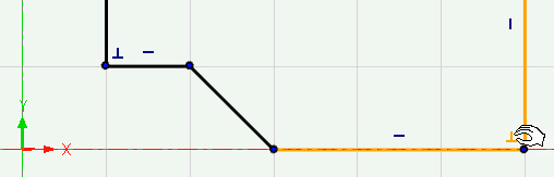
If the mouse cursor is placed on a blue indicator or red constraint, an orange color appears on the lines that together have the relation that the indicator or constraint corresponds to.
Constructionlines-> Dark blue
Dark blue thin lines mean that the line is of type ConstructionGeometry and that it will not create any 3D geometry from these lines in a sketch that then builds a Shapefeature of any kind. It is usually used as a reference (construction line) to work against and can also be a convenient alternative to removing them completely. You can compare it to "extinguishing" (suppressing) lines instead of removing them.
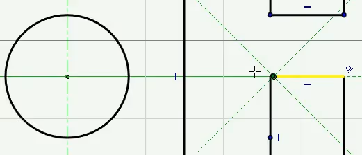
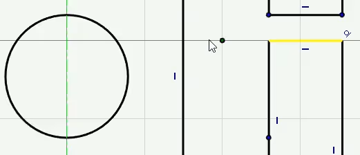
Highlighted lines -> Yellow
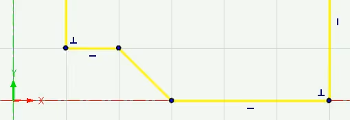
Yellow lines mean that they have been highlighted by the mouse cursor and will be affected by the command being run, or that they are statically moved in the sketch if there are multiple lines highlighted in yellow.
This is also a form of "light constraints" that are only used "temporarily in the moment" and then released as soon as the line is deselected with a simple left click in the plane of the sketch or via [Esc]. Very fast, smooth and powerful, which makes it possible to avoid having to create constraints that are more permanent and that you always have to deal with.
Faultylines -> Magenta/Pink
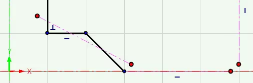
When you finish the work in the sketch and finish to create the 3D geometry, you may encounter different types of problems for various reasons. Intersecting lines or lines with red endpoints appear as thin lines with a magenta (pink) color.
Tip: If the pink color of the line does not return to the "correct color" - try drawing a new line and deleting it, or trimming a line and undoing it. This usually updates the graphics and the color of the lines.
More on this below under point 14) How best to deal with different types of "problems" when they arise.
Offset Spline -> Cyan Blue
When using the Offset command on a Spline curve, the copy turns cyan blue.
Ifyou choose to use parametric control of lines in the sketch, there is a lot to consider. The lines should usually not be able to be moved or dragged "freely" with the mouse pointer and some, many or all lines are controlled by other geometries or by numbers and rules in the parameter table.
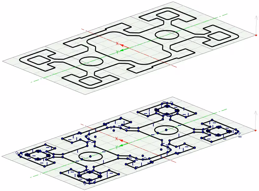
Fully Defined Sketch
When all lines in a Sketch are completely "controlled" by constraints and fixed dimensions, the Sketch is called "fully defined". All lines then have a green color and you can no longer "freely" drag endpoints or lines with the mouse cursor. The shape handles also completely lose their function and you might as well turn off the display of these via Shape Properties.
Depending on the shape of the geometry, a fully defined Sketch may be a requirement to be able to parameterize a profile in a fully predictable way (regardless of the CAD system).
As we can see from the picture, there are certain criteria that need to be met. Here are some common requirements;
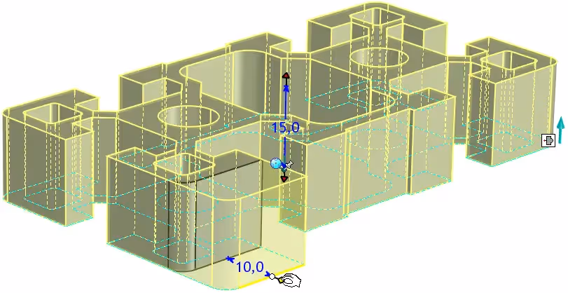
Sketch 13 - Parameter table with the Sketch in IRONCAD
In this video, a parameterized fully defined rectangle is controlled via Edit Cross-section on a Block, where the lower left corner of the rectangle is locked to the origin. The vertical and horizontal lines are locked and dimensioned. These dimensions can then be linked and controlled via the parameter table.
If you are interested in learning more about how to parameterize models in IRONCAD , you can read more about it in a separate support blog post.
First ofall - it is not possible to finish a sketch building a Shape -feature if any of these three "problems" have occurred in the sketch. If this happens and you see this message, choose either Edit Cross-Section (green highlight) or Create Default Shape (yellow highlight).
Avoid clicking on Cancel or the cross (red marks), as these options will take you back to before you started editing the sketch!
Empty sketch
This one is perhaps obvious. It is not possible to execute a sketch that is empty.
Crossing lines
Lines that cross each other will appear in pink/magenta color when trying to finish the Sketch and need to be trimmed or removed.
-video
Duplicate lines
A kind of variant of crossing lines are lines that "lie on top of each other as duplicates" in the sketch. However, upon import, all duplicates will be automatically deleted.
Use the Clear Duplicate command to search for and remove these.
-video
Red end point / "open" profile
A sketch building a Shapefeature cannot be finished if there are endpoints of two or more lines that are not connected to each other. The lines ending in a red endpoint will appear as pink/magenta lines when trying to execute the sketch.
With the Find Gap command, you can find "gaps" between red endpoints within a range of the dimension you set. It does not have to be a "gap" between lines, but can be a simple line with each end marked in red.
Zero length line
You can accidentally click out "an extra point" at the end of a line, resulting in a "zero length line". This "zero-length line" is very poorly visible but actually appears as a "slightly larger endpoint" behind a "regular endpoint". By box checking around the endpoint and then pressing [Delete], the point disappears and you can finish the sketch.
When importing a DWG or DXF file, these "zero" lines should automatically be sorted out and disappear.
-video
Answer: Here we publish tips, guides, news and solutions for those who work with IRONCAD and Design Data Manager (DDM). The blog covers everything from basic functions to advanced workflows, helping you to optimize your design work. You'll find examples of smart shortcuts, practical instructions, solutions to common problems, and best practices for product design, mechanical design, and product data management.
Answer: Our guides and tips are designed for both beginners and experienced CAD users. They are aimed at designers, engineers and project managers who want to work more efficiently with IRONCAD and DDM, improve the design process, reduce mistakes and save time in product development.
Answer: We regularly publish new articles when the software is updated, when new features are introduced, or when our users ask for solutions to specific problems. The blog is therefore a reliable source for keeping up to date and getting tips that make everyday CAD work easier.
Answer: Many of our instructions and tips work in multiple versions, but we clearly indicate if an article applies to a specific version. We strive to make the content useful for older versions as well, and also provide recommendations on how to adapt workflows to the version you are using.
Answer: Absolutely! If you can't find the solution in the blog, you can contact our technical support via solidmakarna.support. Our experts will help you with everything from installation and configuration to advanced features in IRONCAD and DDM, so you can solve problems quickly and efficiently.
Answer: Yes! We appreciate suggestions from our users. If you have questions, tips or want us to address a specific issue in IRONCAD or DDM , please contact us via our contact form and we will prioritize relevant topics in future posts.
Answer: The blog contains, among other things:
Practical step-by-step guides to help you use IRONCAD and DDM more effectively.
Productivity and workflow tips for faster design and construction.
Solutions to common problems encountered by users in CAD programs.
Updates and news on new features, versions and improvements.
Best practices for data management and project organization in DDM.
Answer: All tips and guides are directly applicable in daily work. For example, you can use shortcuts and smart features in IRONCAD to speed up modeling, structure files better in Design Data Manager, or follow our step-by-step solutions for specific problems that often come up in design projects.
Answer: We strive to ensure that all guides and tips are relevant to the latest versions of IRONCAD and DDM. We also clearly mark when a post applies to an older version, so you always know if the instruction is directly applicable to your system.
Answer: Yes! Many of our users share the articles with colleagues and use them as internal training materials. The blog is a great complement to formal training and helps teams learn features faster, avoid mistakes, and standardize workflows in IRONCAD and DDM.