Looks like you don't have ESC button on your device
Download IronCAD DCS
Choose one of the following options
trial versionHas a license
Looks like you don't have ESC button on your device
Choose one of the following options
trial versionHas a license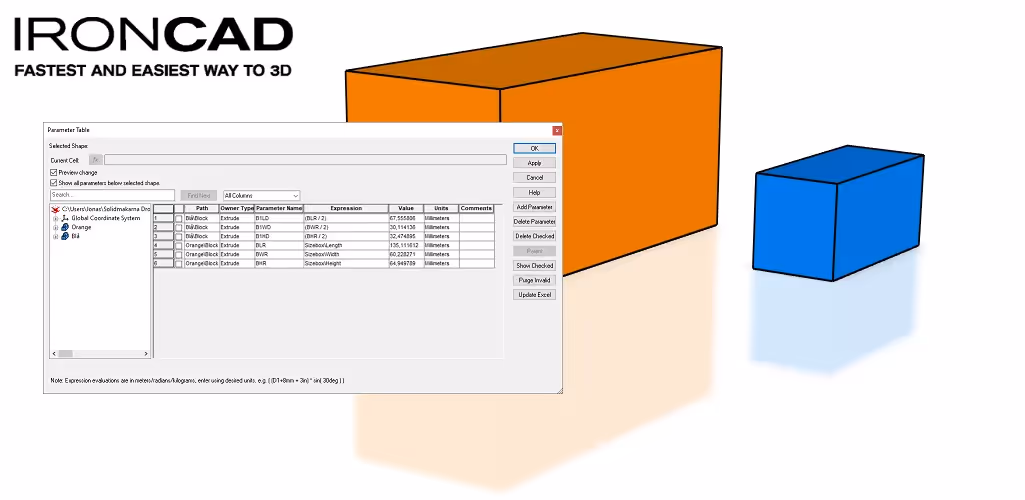

Emil Rindell

Jonas Bryntesson

Henrik Andersson
2023-11-15
Emil Rindell
Jonas Bryntesson
Henrik Andersson
2023-11-15
Even though IRONCAD primarily does not use locked relations in the form of constraints (it does not provide more control or precision to control geometric changes through a parameter table), you can, if necessary, create features, parts and assemblies that are fully or partially controlled by constraints and parameterized dimensions. This is particularly useful for standard table-driven components.
Here we'll go through some basics that are good to know. We start with the fastest way to parameterize a so-called Innovative Part which basically consists of a simple extrusion (Block) that we drop from a catalog in the 3D scene.
It is quick and easy to add parametric controls to the Sizebox handles that control the size of a feature, part or assembly. By default, the Sizebox handles are primarily displayed on Shape features such as a Block, but it is also possible to add the corresponding Sizebox handles at the part or assembly level.
The video below shows a quick way to use the Sizebox handles to parameterize a so-called Innovative Part which basically consists of a simple extrusion (Block) that we have released from a catalog in the 3D scene. The video also goes through why certain steps are performed in a certain way and what to consider. For example, tips on the names of the parameters you create and how the Anchor Point affects the direction in which a change in size of a parameter takes place.
Tip: At the bottom right, there is a list of chapters, so you can easily jump back and forth between different parts of the video.
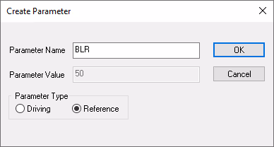
Very briefly described, you can right-click on a Sizebox handle to create a parameter that controls the shape of the geometry in that particular direction. The parameter used in the video that controls the shape of the geometry via the parameter table is called the Driving Parameter.

You can also choose to continue using the differently colored round Sizebox handles "as usual" by being able to drag them freely and instead use parameters to read the current value of the handle. This is called a Reference Parameter and is created in a similar way.
It is therefore important to know whether you want to continue to be able to work with the Sizebox handles ( Reference option) or whether the parameter table should be the one that controls the shape of an object ( Driving option).
Download the model developed in the video.
Here is a very simple example where we combine "free" Sizebox handles with locked dimensions in the sketch for an extrusion. When you pull the outer/larger model, the inner/smaller model is forced to follow.
Another thing that is shown at the end of the video is how to control the precision when dragging "freely" with the Sizebox handles, both in terms of max/min-size but also what size the incremental steps should be.
Download the model developed in the video.
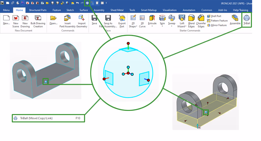
A simple way to control the number of copies of one or more features in a parametric model is by using a pattern, usually called Pattern. This can be done with TriBall but also via the command Pattern Feature. No matter which way you create patterns of features, you can always control these from the parameter table.
Here is a video without sound that shows how to create a parametric model where the number of certain features is determined by the length of the part.
Download the model developed in the video.
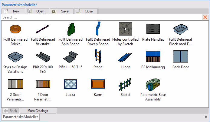
We have developed a large number of parametric models over the years and some of them are available through a catalog called ParametricModels.icc.
That catalog might already be available on your computer, through our add-on installation Swedish Standard Customization. Check via Catalog Open, under the folder for Scene catalogs if the ICC file is available there. Otherwise, you can download it via the link in the text above.
There are a couple of different series of instructional videos dealing with parametric models in IRONCAD on the training site IronCAD Academy. (Note: These videos have Swedish voice).
First, we have a series of 7 videos that go through completely different models and ways to parametrically control features in IRONCAD. First up is a simple round tile controlled by two circles with locked dimensions in the sketch.
Remember that you can see all our training videos in the list on the left (via the link above).
These 7 videos were created with version 2017 and therefore differ to some extent around menu and catalog content. The round Sizebox handles all have a red color and other colors also differ slightly with, for example, the sketch's white instead of black color on lines and the "gradient" blue-white background.
There is also a series of 15 videos on how to create a fully parameterized wall cabinet in IRONCAD.
The add-on IronCAD Mechanical has several tools for handling parameterized parts. Many of the basic functions found in e.g. the ICM Mech catalog, such as screws, nuts, beams, etc. are standard table-controlled components and you can easily build your own components with a similar function.
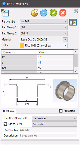
Find out more about the PROActiveParts tool via the IC Mechanical online manual.
By default, IRONCAD does not use constraints as the primary means of controlling the position of either objects in 3D space or lines in the 2D sketch.
Instead, the position in 3D space or in the 2D plane is the primary property that controls objects in 3D space or 2D plane and this position is handled with special (usually unique) tools and therefore it is very often enough to just select the objects to be changed at the time of the change itself. However, it is I as a user who controls, so when I think constraints are needed (because nothing else solves a particular situation better), you can apply it where it fits.
This also means that if I were to remove one or more constraints, there is also the security that the current XYZ position in space is always there and "catches" the model if constraints and relations are missing = more control to you as a user!
However, once you have started using constraints, there is a high risk that you will have to keep placing more constraints until all objects or lines in the sketch are "fully defined". This means that changes can only be made in one or more predetermined ways, but no other way is accepted.
For some parts, smaller assemblies and standard components, it can be very smart and useful and save a lot of time when changes are made only in fully predetermined ways.
However, a recognized disadvantage of constraints is that an unforeseen change is sometimes not possible to implementas it may "collide" with one or more other existing constraints. One then needs to either remove constraints, with the risk that the model "collapses", or start from scratch with constraints that take into account the change one wants to implement.
Since constraints are usually not used or needed in the daily work with IRONCAD, we do not use it in our basic training. But we have a lot of other video material that explains how it can be used in practice and there it is mainly when working with mechanisms that you need to place relationships / constraints between the moving parts.
That said, there are plenty of examples of using geometrically parameterized models in IRONCAD, where the position is completely controlled by constraints. However, this is (largely) only useful for standard table-driven components or reusable assemblies of details that always follow the same completely predetermined rules.
The Swedish company Nefab, with hundreds of IRONCAD around the world, has built countless parameterized 3D models of their different types of packaging and uses IRONCAD in a very "broad way". Their products produced in IRONCAD are usually completely parameterized via the dimensions that need to be specified in order for the packaging and all its sub-components to have the right number and dimensions. Parameter-controlled - but still easy to change, often via the Sizebox handles.
What is remarkable is that there is not a single constraint or relationship between the 3D models used in everything from the customer products handled in the packaging to the "one-off" designed manufacturing machines! This is because constraints in themselves do not add any value to these types of models and completely avoid the risk of having to start over when an unforeseen change needs to be introduced!
Answer: Here we publish tips, guides, news and solutions for those who work with IRONCAD and Design Data Manager (DDM). The blog covers everything from basic functions to advanced workflows, helping you to optimize your design work. You'll find examples of smart shortcuts, practical instructions, solutions to common problems, and best practices for product design, mechanical design, and product data management.
Answer: Our guides and tips are designed for both beginners and experienced CAD users. They are aimed at designers, engineers and project managers who want to work more efficiently with IRONCAD and DDM, improve the design process, reduce mistakes and save time in product development.
Answer: We regularly publish new articles when the software is updated, when new features are introduced, or when our users ask for solutions to specific problems. The blog is therefore a reliable source for keeping up to date and getting tips that make everyday CAD work easier.
Answer: Many of our instructions and tips work in multiple versions, but we clearly indicate if an article applies to a specific version. We strive to make the content useful for older versions as well, and also provide recommendations on how to adapt workflows to the version you are using.
Answer: Absolutely! If you can't find the solution in the blog, you can contact our technical support via solidmakarna.support. Our experts will help you with everything from installation and configuration to advanced features in IRONCAD and DDM, so you can solve problems quickly and efficiently.
Answer: Yes! We appreciate suggestions from our users. If you have questions, tips or want us to address a specific issue in IRONCAD or DDM , please contact us via our contact form and we will prioritize relevant topics in future posts.
Answer: The blog contains, among other things:
Practical step-by-step guides to help you use IRONCAD and DDM more effectively.
Productivity and workflow tips for faster design and construction.
Solutions to common problems encountered by users in CAD programs.
Updates and news on new features, versions and improvements.
Best practices for data management and project organization in DDM.
Answer: All tips and guides are directly applicable in daily work. For example, you can use shortcuts and smart features in IRONCAD to speed up modeling, structure files better in Design Data Manager, or follow our step-by-step solutions for specific problems that often come up in design projects.
Answer: We strive to ensure that all guides and tips are relevant to the latest versions of IRONCAD and DDM. We also clearly mark when a post applies to an older version, so you always know if the instruction is directly applicable to your system.
Answer: Yes! Many of our users share the articles with colleagues and use them as internal training materials. The blog is a great complement to formal training and helps teams learn features faster, avoid mistakes, and standardize workflows in IRONCAD and DDM.