Looks like you don't have ESC button on your device
Download IronCAD DCS
Choose one of the following options
trial versionHas a license
Looks like you don't have ESC button on your device
Choose one of the following options
trial versionHas a license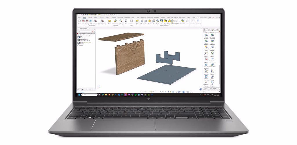

Emil Rindell

Jonas Bryntesson

Henrik Andersson
December 11, 2025
Emil Rindell
Jonas Bryntesson
Henrik Andersson
December 11, 2025
Using pins and holes makes it easy to place different parts in the right place before welding, for example. It is used for fixtures, among other things, but also for general machine construction. Parts designed in IRONCAD often IRONCAD via DXF to a laser cutting machine that creates parts with exact dimensions.
This feature is included in IC Mechanical – a powerful add-on to IRONCAD makes it quick and easy to create mechanical details. The tool works equally well on both Innovative Parts and Sheet Metal Parts. Read more about IC Mechanical and about IRONCAD .
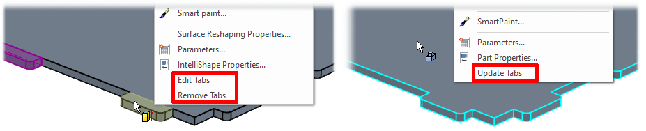
Here we show you how to use Create Tabs and Slots to quickly add tabs to one edge and automatically create matching slots on the opposite part.
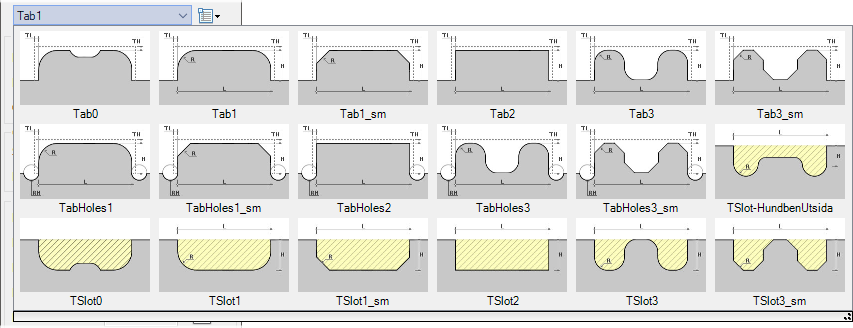
Drag and drop the tool onto the edge where you want the tabs to be.
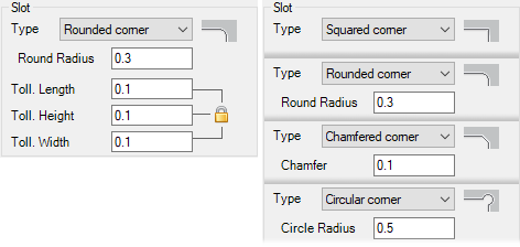
The dialog box opens where you select the tap type and all dimensions.
Want to add your own pins? Scroll down for more information.
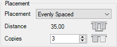
Select how the pins should be distributed along the edge:
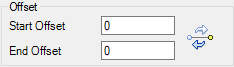
Here you specify the distance from the start and end of the edge. The arrow icon quickly reverses the start and end values.
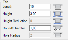
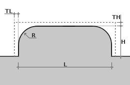
All dimensions for the selected pin:
Here you control how much larger the hole around the pin should be (tolerance). The padlock locks the same value for all directions.
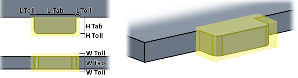
The yellow semi-transparent preview shows exactly how the hole will look on the opposite side.
The video above shows how to create your own pins and holes. Note that IronPROXT was the previous name for this add-on. It isMechanical called ICMechanical .
Custom pins are created as parametric .ics files and must be parametric.
Example:
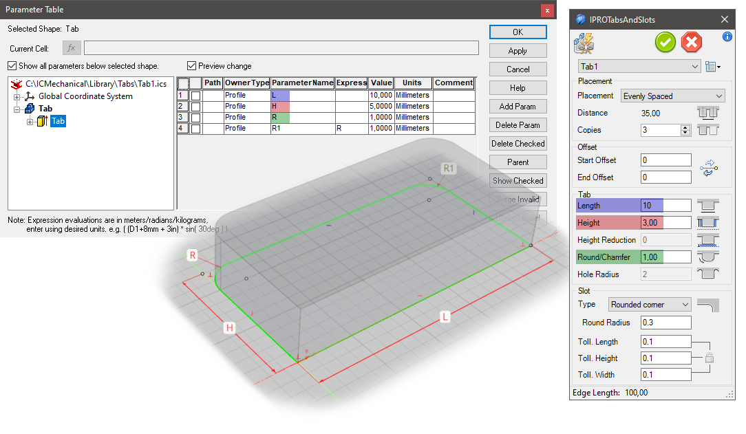
Tab1.ics (the tab itself) The IntelliShape name should be Tab and contain the following parameters:
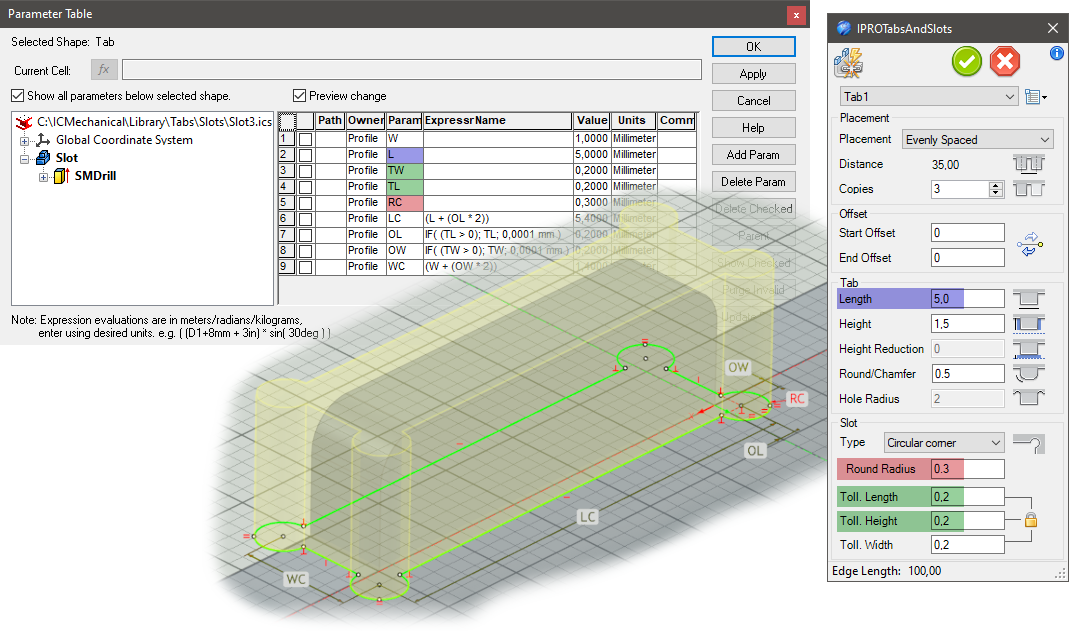
Slot3.ics (the hole created on the opposite part) The IntelliShape name should be SMDrill and contain:
Save the files in ..\ICMechanical\Library\Tabs and ..\ICMechanical\Library\Slots (can be changed with IPROSetting)
Tip: Add a .jpg file with the same name as the .ics file to display a preview in the drop-down list.
Answer: Here we publish tips, guides, news and solutions for those who work with IRONCAD and Design Data Manager (DDM). The blog covers everything from basic functions to advanced workflows, helping you to optimize your design work. You'll find examples of smart shortcuts, practical instructions, solutions to common problems, and best practices for product design, mechanical design, and product data management.
Answer: Our guides and tips are designed for both beginners and experienced CAD users. They are aimed at designers, engineers and project managers who want to work more efficiently with IRONCAD and DDM, improve the design process, reduce mistakes and save time in product development.
Answer: We regularly publish new articles when the software is updated, when new features are introduced, or when our users ask for solutions to specific problems. The blog is therefore a reliable source for keeping up to date and getting tips that make everyday CAD work easier.
Answer: Many of our instructions and tips work in multiple versions, but we clearly indicate if an article applies to a specific version. We strive to make the content useful for older versions as well, and also provide recommendations on how to adapt workflows to the version you are using.
Answer: Absolutely! If you can't find the solution in the blog, you can contact our technical support via solidmakarna.support. Our experts will help you with everything from installation and configuration to advanced features in IRONCAD and DDM, so you can solve problems quickly and efficiently.
Answer: Yes! We appreciate suggestions from our users. If you have questions, tips or want us to address a specific issue in IRONCAD or DDM , please contact us via our contact form and we will prioritize relevant topics in future posts.
Answer: The blog contains, among other things:
Practical step-by-step guides to help you use IRONCAD and DDM more effectively.
Productivity and workflow tips for faster design and construction.
Solutions to common problems encountered by users in CAD programs.
Updates and news on new features, versions and improvements.
Best practices for data management and project organization in DDM.
Answer: All tips and guides are directly applicable in daily work. For example, you can use shortcuts and smart features in IRONCAD to speed up modeling, structure files better in Design Data Manager, or follow our step-by-step solutions for specific problems that often come up in design projects.
Answer: We strive to ensure that all guides and tips are relevant to the latest versions of IRONCAD and DDM. We also clearly mark when a post applies to an older version, so you always know if the instruction is directly applicable to your system.
Answer: Yes! Many of our users share the articles with colleagues and use them as internal training materials. The blog is a great complement to formal training and helps teams learn features faster, avoid mistakes, and standardize workflows in IRONCAD and DDM.