Looks like you don't have ESC button on your device
Download IronCAD DCS
Choose one of the following options
trial versionHas a license
Looks like you don't have ESC button on your device
Choose one of the following options
trial versionHas a license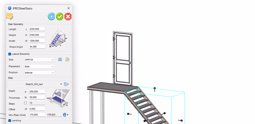

Emil Rindell

Jonas Bryntesson

Henrik Andersson
February 19, 2026
Emil Rindell
Jonas Bryntesson
Henrik Andersson
February 19, 2026
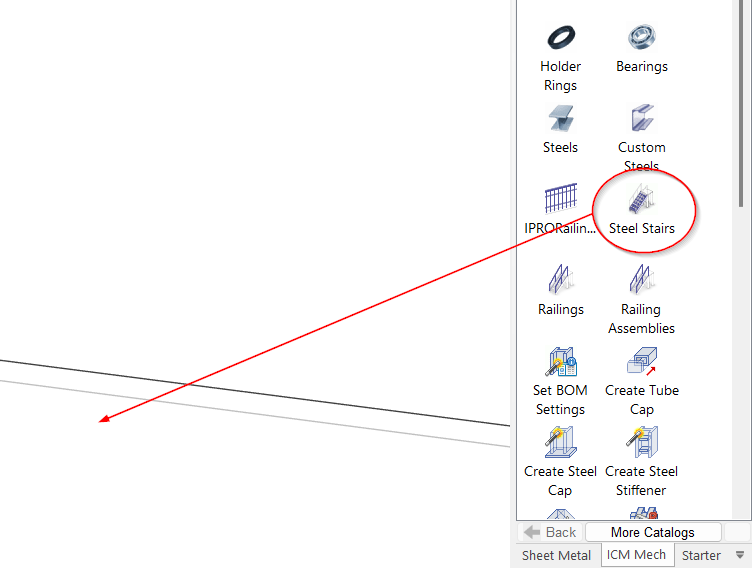
You can find the Steel Stairs command in the ICM Mech catalog. It is used to place steel stair structures consisting of steps and stringers, as well as a simple mezzanine floor, directly into your 3D scene.
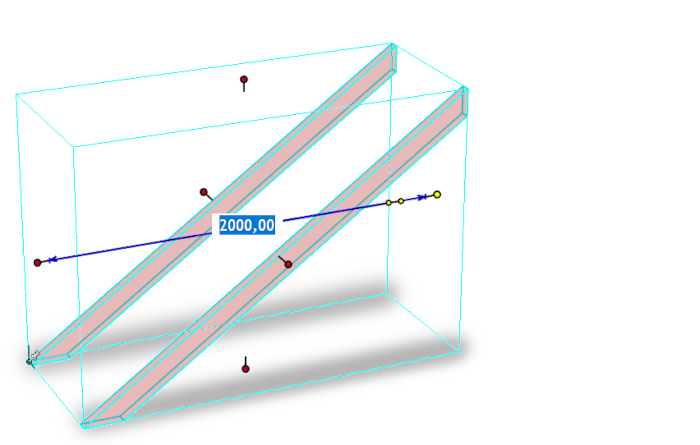
Drag the tool icon in the 3D scene and set the options. To change dimension, drag the Sixebox handle of the preview volume or enter the values in the dialog box.
The Steel Stairs dialog box is divided into four different sections: Stair Geometry, Lateral Elements, Step, and Landing. Below is a description of each of these sections.
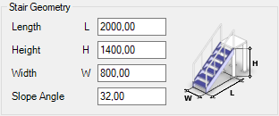
In the first section, you can set the overall dimensions of the staircase (or drag the Sizebox handles in the preview volume).
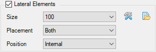
In the second part, you can select the type of staircase stringer, its size, location (both sides, right side only, left side only), and position (inside or outside the preview volume).
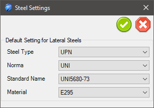
The first icon allows you to change the steel type, e.g. UPE or UPN profile. The second icon allows you to use your own steel profiles. Read further down in the post for more information about this.
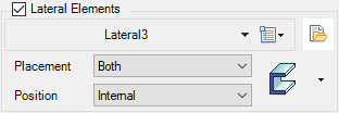
When you choose to use your own steel profiles, a drop-down button appears for selecting the profile, and a button for setting the size is also displayed.
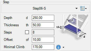
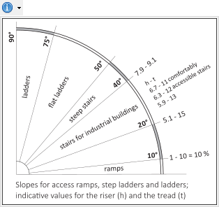
In the third section, you can select the type of steps, their size, the offset in relation to the side parts, and the minimum step height between the steps (or – slightly above – "force" the number of steps). Via the info icon, you can display a diagram for the correct dimensioning of the staircase.
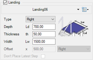
The fourth section is used to set up a simple mezzanine floor. Here you can select the type (straight, right, left, or centered) and specify its size.
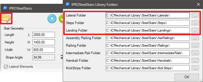
The first icon at the top left of the dialog box opens the settings for the folders in the Steel Stairs library, where you can save custom components such as stringers, steps, mezzanine floors, and railings, as well as kick plates.
In order to adapt the elements to the selected dimensions, all models that make up the staircase must be parametric and saved in the respective folder in the library.
Here are two examples of stringers:
Lateral1 is a part with a forward-facing parametric section:
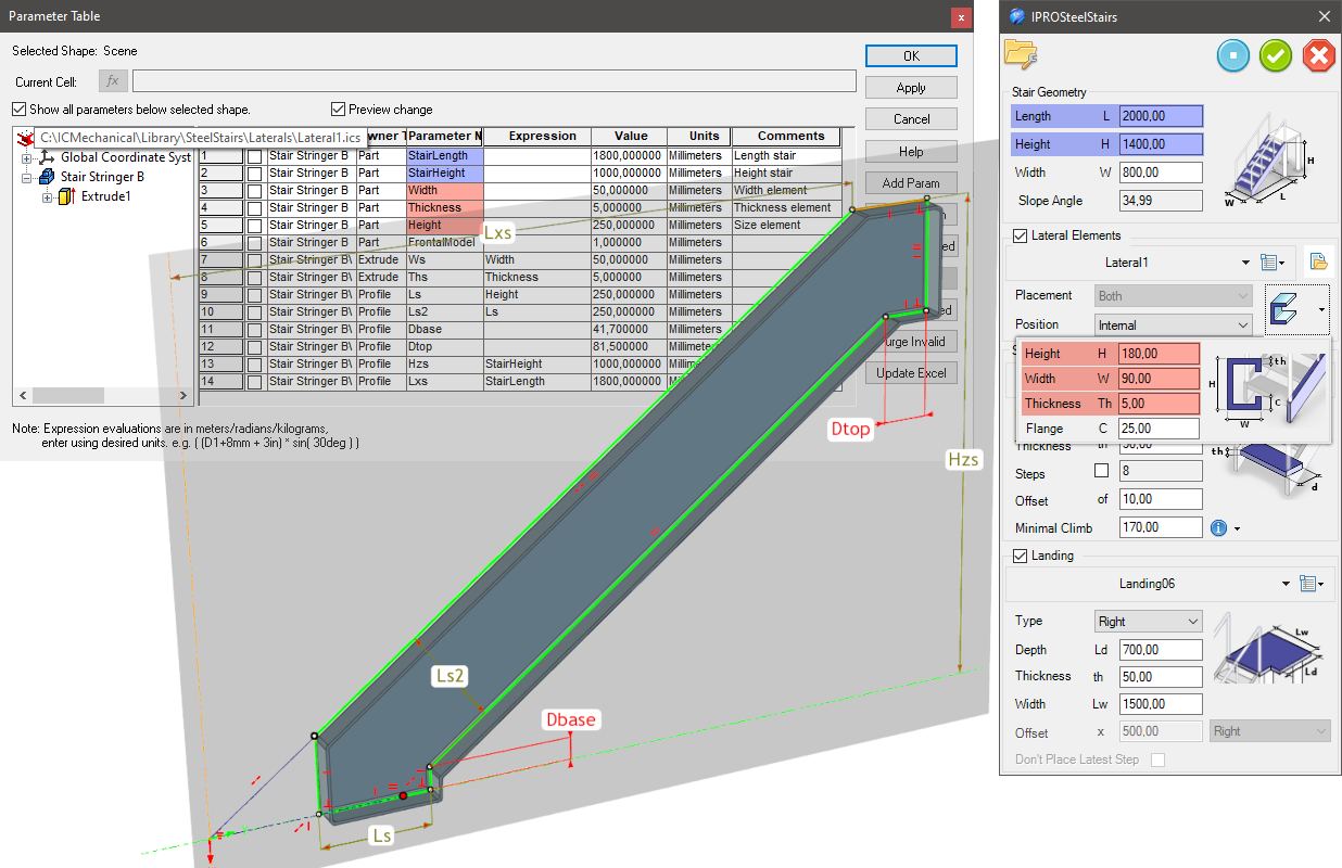
In order to adapt the guardrail to the size of the staircase, it must include the following parameters:
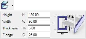
Lateral2 is a part with a lateral parametric section (the section of the customized steel):
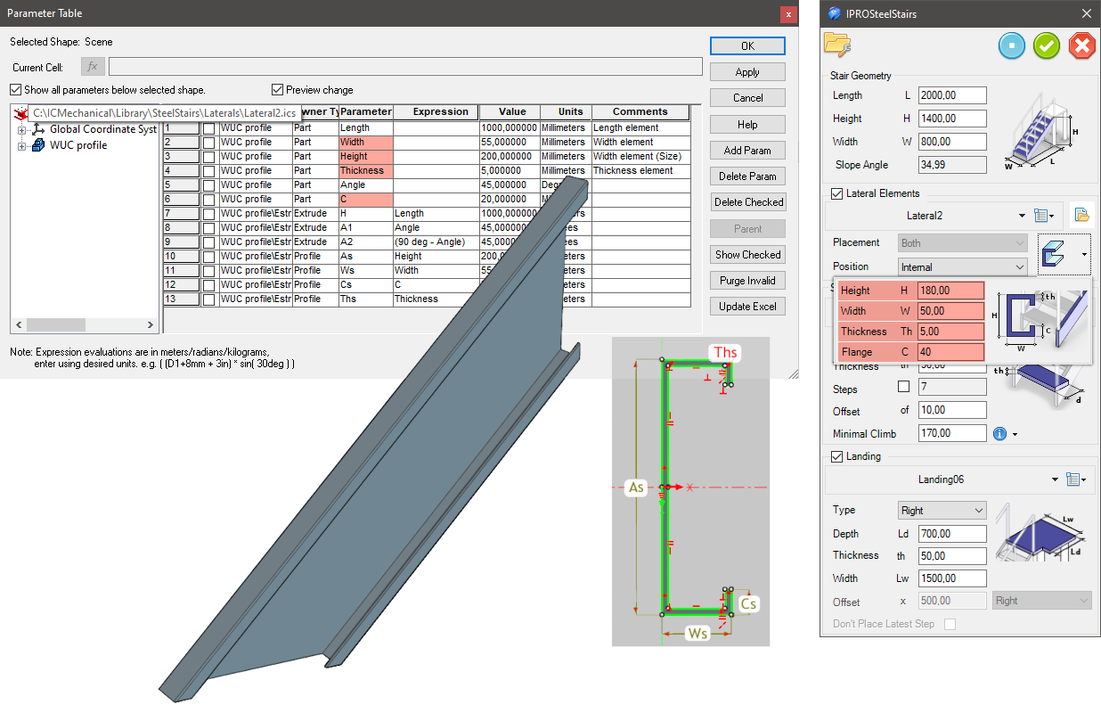
In this case, the Length parameter (for the profile) does not correspond to the length of the staircase, but is used to calculate the hypotenuse between the Length (L) and Height (H) of the staircase.
Here are two examples of steps:
Step03_SM is a sheet metal part:
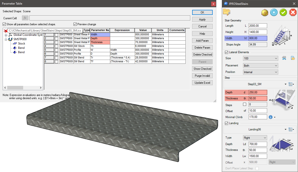
In order to adapt the steps to the size of the staircase, the steps must contain the following parameters (at the part or assembly level):
Optional, only if screws are available:
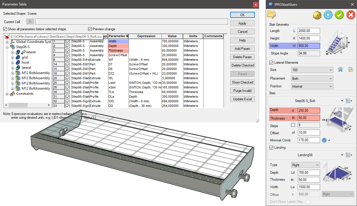
Step06-S_Bolt is an assembly of a step with a grid (simplified) and screws, nuts, and washers:
Answer: Here we publish tips, guides, news and solutions for those who work with IRONCAD and Design Data Manager (DDM). The blog covers everything from basic functions to advanced workflows, helping you to optimize your design work. You'll find examples of smart shortcuts, practical instructions, solutions to common problems, and best practices for product design, mechanical design, and product data management.
Answer: Our guides and tips are designed for both beginners and experienced CAD users. They are aimed at designers, engineers and project managers who want to work more efficiently with IRONCAD and DDM, improve the design process, reduce mistakes and save time in product development.
Answer: We regularly publish new articles when the software is updated, when new features are introduced, or when our users ask for solutions to specific problems. The blog is therefore a reliable source for keeping up to date and getting tips that make everyday CAD work easier.
Answer: Many of our instructions and tips work in multiple versions, but we clearly indicate if an article applies to a specific version. We strive to make the content useful for older versions as well, and also provide recommendations on how to adapt workflows to the version you are using.
Answer: Absolutely! If you can't find the solution in the blog, you can contact our technical support via solidmakarna.support. Our experts will help you with everything from installation and configuration to advanced features in IRONCAD and DDM, so you can solve problems quickly and efficiently.
Answer: Yes! We appreciate suggestions from our users. If you have questions, tips or want us to address a specific issue in IRONCAD or DDM , please contact us via our contact form and we will prioritize relevant topics in future posts.
Answer: The blog contains, among other things:
Practical step-by-step guides to help you use IRONCAD and DDM more effectively.
Productivity and workflow tips for faster design and construction.
Solutions to common problems encountered by users in CAD programs.
Updates and news on new features, versions and improvements.
Best practices for data management and project organization in DDM.
Answer: All tips and guides are directly applicable in daily work. For example, you can use shortcuts and smart features in IRONCAD to speed up modeling, structure files better in Design Data Manager, or follow our step-by-step solutions for specific problems that often come up in design projects.
Answer: We strive to ensure that all guides and tips are relevant to the latest versions of IRONCAD and DDM. We also clearly mark when a post applies to an older version, so you always know if the instruction is directly applicable to your system.
Answer: Yes! Many of our users share the articles with colleagues and use them as internal training materials. The blog is a great complement to formal training and helps teams learn features faster, avoid mistakes, and standardize workflows in IRONCAD and DDM.