Looks like you don't have ESC button on your device
Choose one of the following options
trial versionHas a license

Looks like you don't have ESC button on your device
Choose one of the following options
trial versionHas a licenseIRONCAD is a comprehensive 3D CAD program. In the field of hydraulics, it is used for 3D valve blocks, cylinders, and power units; 2D hydraulic schematics; and pipe and hose routing—all within the same model.
Over 1000+ satisfied customers



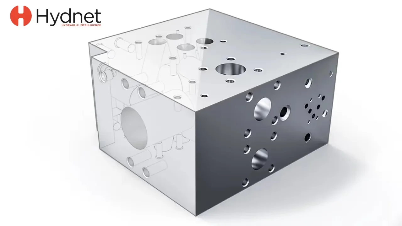
Valve block with channels in 3D
Hydraulic diagrams in DRAFT
Pipes and hoses of the same model
IRONCAD IRONCAD is a 3D CAD program for industrial design, ranging from machinery and sheet metal to layouts and fixtures. What sets apart from traditional CAD systems is the freedom of choice: you decide for yourself how to model. Design freely using drag-and-drop and TriBall, add constraints and parametric dimensions only where they’re needed, and modify imported geometry directly without a history tree. These methods can be combined within the same , and the entire assembly is contained in a single file. This page shows how hydraulic companies use it. part
This video is SMC Automation’s own presentation of the company: the world’s largest manufacturer of industrial pneumatics, headquartered in Stockholm and with over 9,000 components in stock. Custom valve cabinets, hose routing, and pneumatic schematics are designed at IRONCAD, from the sales representative’s layout sketch to the assembly drawing with a bill of materials. Would you like to see what your next unit would look like at IRONCAD?
Book a demo and we’ll show you!
You select the method for each part, not for each program.
All three work in the same file, and they can be combined in a single aggregate.
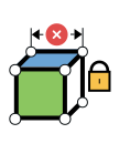
For cylinders and blocks that require variant management. Lock the stroke, piston diameter, and port spacing using constraints, and the next size will be recalculated without you having to redraw it.
MOST POPULAR
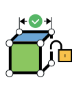
The standard method for assemblies and blocks. Drag and drop pumps, filters, and valves from the catalog, position them using TriBall, and reposition them if the customer wants the connection on the other side. No mandatory constraints.
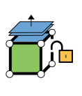
For suppliers' STEP files of pumps, motors, and valves. Select a surface and drag, add fasteners, and adjust the flange. No history required.
The block is modeled as a solid. Hole patterns, threaded holes, and channels are imported from the catalog with the correct diameter, thread, and depth, and the holes are created as they are placed.
Display the block as transparent, or invert it and view the channels as positive images; that way, you can immediately see if the channels align correctly.
The cylinder is built based on stroke length, piston diameter, and connection type, and is saved in the catalog so that the next order starts with a finished cylinder that can be modified.
Seals, lock rings, and bolted joints are retrieved from IC Mechanical. The rendering for the customer presentation is created in KeyShot directly from the model.

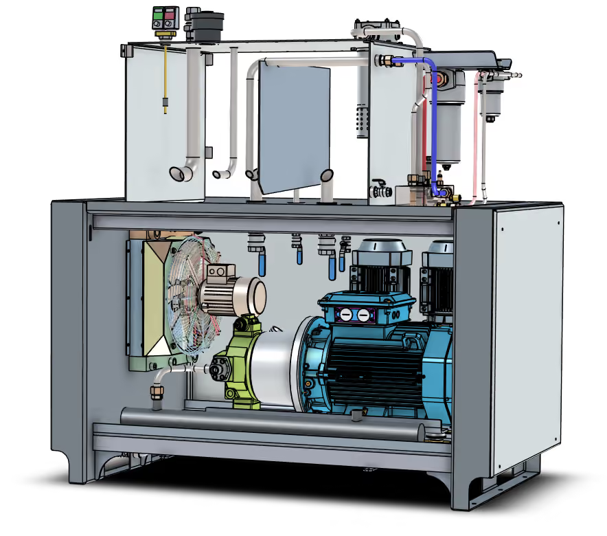
Pipes, flanges, and couplings are routed between connections using the Piping tool in IC Mechanical. Hoses are routed as 3D curves with bend radii that match the hose type.
Lengths and items are listed in the bill of materials. If a valve is moved, the pipe moves with it.
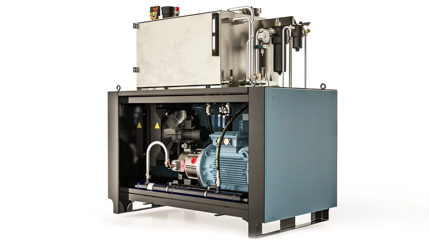
The entire unit is contained in a single file: the tank is made of sheet metal, the frame is made of bent sheet metal, and the motors, pumps, and filters are imported from suppliers. The industrial hydraulics team sits in front of the customer and modifies the design directly on-site in real time.
“We can do this without running the risk of all the typical errors that are common in other constraint-based systems,” says Kent Wahlgren, a design engineer at Industrihydraulik.
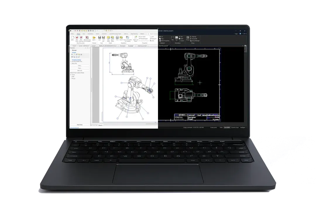
ICD renders blocks, cylinders, and assemblies with views, sections, ISO-compliant dimensions, and an automatic bill of materials. DRAFT features a traditional 2D interface similar to AutoCAD, for schematics and pure 2D drawings.
Both follow the model when the design changes. The customer receives a 3D model, a diagram, and a drawing from the same project.
Hydnet builds its valve blocks using off-the-shelf components from its own catalogs: cartridge valves, filters, and fittings that are inserted into the block—much like building with Legos.
The block is displayed to the customer in 3D early in the project, with the channels visible through the material. The schematic and the drawing are part of the same solution, which helps reduce errors along the way.
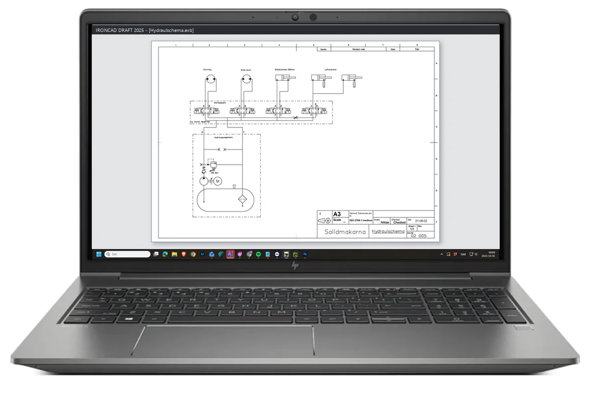
The schematic is drawn in DRAFT, IRONCAD's built-in 2D environment, using symbol libraries for pumps, valves, filters, cylinders, and accumulators. Custom symbols can be added to the library.
The drawing is included in the same project as the 3D model, opens the customer's DWG and DXF files, and is included in the documentation provided to the customer.

Tanks, covers, and brackets made of bent sheet metal, including dimensions and DXF files.
Channels and cross-sections are freely sketched in 2D. Use parameters whenever you want—they're not mandatory.

Cartridges, valves, couplings, and custom drag-and-drop blocks.

Position and align pumps, valves, and connections precisely, without constraints.
Hydraulic fixtures with patented hydraulic systems in milled plates that are stacked to form channel systems, including for Husqvarna. IRONCAD for 20 years.

“We use IRONCAD because it’s both easy and flexible to work with, and it’s very fast to go from a quick sketch to a finished design.”
Linus Gunnarsson, Tooli Hydraulic Fixture Tools AB
The world's largest manufacturer of industrial pneumatics. Custom valve cabinets are built in IRONCAD using over 9,000 drag-and-drop components, and the pneumatic schematics are drawn in the same program.
“We use IRONCAD for everything, including simple 2D pneumatic diagrams. We can then add these to the assembly drawing if the customer wishes.”
Pål Hallström, SMC Automation AB
Cartridge valves, valve blocks, and hydraulic filters for mobile, industrial, and marine applications, from offices in Stockholm, Gothenburg, and Malmö. In-house component libraries at IRONCAD and hydraulic schematics within the same solution.

Complete hydraulic systems, valve blocks, and power units, exported worldwide. Sheet metal tanks, imported pumps and motors, and piping all in the same file.
“We’ve compared it with other 3D CAD solutions and found that none of them come close to the flexibility and speed that IRONCAD offers. We really appreciate being able to sit with the customer and modify the design right there on the spot, in real time.”
Kent Wahlgren, Design Engineer, Industrihydraulik Sweden AB

Yes. In " DRAFT," which is part of " IRONCAD," the schematic is drawn using standard symbol libraries for pumps, valves, filters, cylinders, and accumulators. The schematic is saved in the same project as the 3D model.
The block is modeled as a solid, and channels and cartridge holes are created as smart shapes with the correct diameter, thread, and depth from the catalog. The channels can be modified directly in 3D, and the block is displayed as transparent to verify that the channels align.
Yes. STEP and IGES files from Parker, Bosch Rexroth, Danfoss, and others open directly, and with Translator , SolidWorks and Inventor files open as well. The components are saved in their own folders with attachment points for the next assembly.
Yes. Pipes and hoses are routed between the connections in the unit, with bend radii and lengths specified in the bill of materials. If the location of a valve is changed, the hose is adjusted accordingly.
Using MultiPhysics for IRONCAD , pressure is applied to the channels and piston, and stress and deformation are displayed on the model. This is sufficient for sizing the parts and lids before the prototype is manufactured.
With Design Data Manager, every block, cylinder, schematic, and drawing is assigned a part number, revision, and searchable properties, regardless of whether the file comes from IRONCAD, SolidWorks, or Inventor. The schematic and the 3D model are kept together in the same revision.
Full version for 30 days, free of charge. Swedish support and training from Solidmakarna.

30-day full version of IRONCAD . No credit card information required, no obligation to purchase.

Install the software, open your own files, and follow the setup wizard in the IronCAD Academy.

We'll show you how IRONCAD fits your specific production needs—in just half an hour.

A 2 + 2-day instructor-led introductory course, or self-paced study. Course instructors who design their own projects in IRONCAD.