Looks like you don't have ESC button on your device
Choose one of the following options
trial versionHas a license

Looks like you don't have ESC button on your device
Choose one of the following options
trial versionHas a licenseIRONCAD is a comprehensive 3D CAD program. In the industrial services sector, it is used for spare parts, mounts, conveyors, and modifications, which are designed directly in 3D using standard components, with drawings and DXF files available the same day.
Over 1000+ satisfied customers


One-time parts without a parametric detour
Standard parts directly in the model
Drawings and DXF Files on the Same Day
IRONCAD IRONCAD is a 3D CAD program for industrial design, ranging from machinery and sheet metal to layouts and fixtures. What sets apart from traditional CAD systems is the freedom of choice: you decide for yourself how to model. Build freely using drag-and-drop and TriBall, add constraints and parametric dimensions only where they’re needed, and modify imported geometry directly without a history tree. These methods can be combined within the same , and the entire assembly is contained in a single file. This page shows how industrial service workshops use it. part
The video is Saltängens Mekaniska’s own presentation of its workshop in Norrköping: over 5,000 square meters, turning capacity up to 13 meters, and lifting capacity up to 30 metric tons, for repairs, welding, and machining of large machine parts. The manhole cover for the Heron and the parts for the chain conveyor are designed in IRONCAD, with the manufacturing data generated directly from the model.
Would you like to see what your next service job would look like in IRONCAD?
Book a demo and we’ll show you!
You select the method for each part, not for each program.
All three work in the same file, and they can be combined in a single 3D model.
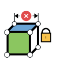
For parts you redesign in multiple sizes—manholes, brackets, railings—lock the division, height, and hole diameter using constraints, and the next size will be recalculated without you having to redraw it.
MOST POPULAR
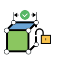
The standard method for one-time jobs. Drag beams, bearings, and bolted connections from the catalog, position them using TriBall relative to the customer’s equipment, and modify them freely if the on-site dimensions turn out to be different. No mandatory constraints.
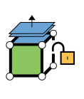
For the customer's STEP files and old models without history. Select a surface and drag it, add the reinforcement, and move the holes. No history is needed.
The customer's old DWG drawing is opened in DRAFT; the STEP file for the existing equipment is added to the scene, or an on-site measurement is sketched in. The new part is built directly onto the base.
Imported geometry is modified without a history tree: add reinforcements, holes, and milled features for the repair.
Beams, pipes, bolted joints, ball bearings, packing boxes, lock rings, and standard wedges are available in the IC Mechanical. Drag them in, drop them in place, and they will appear in the bill of materials with the correct designation.
A motor mount or conveyor component is built in a matter of hours, directly within the assembly without separate part files.
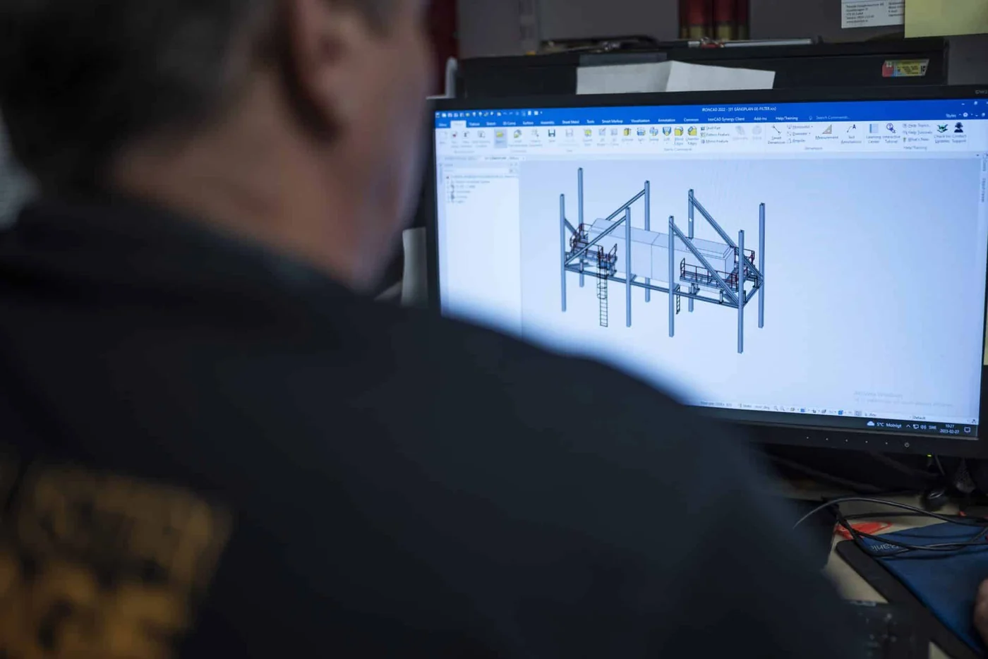
With Steel Stairs in IC Mechanical , a complete steel staircase is brought onto the scene: dimensions, stringers, treads, and landings are configured using a preview feature. Mezzanine levels and escape routes are constructed using profiles from the same catalog.
LN Industrimontage builds escape routes and platforms for the mining, steel, and paper industries in this way.
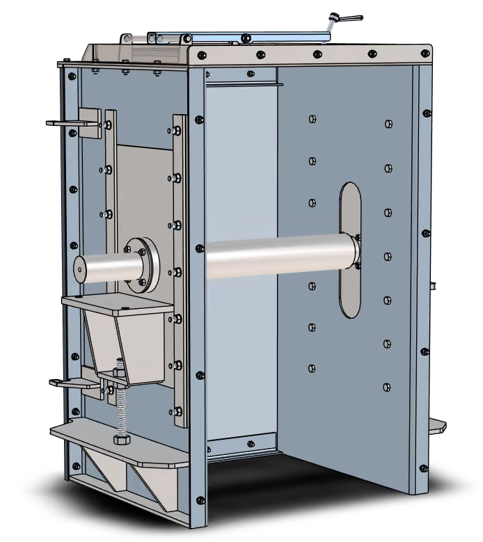
Cisterns, tanks, hatches, and protective covers are constructed in Sheet Metal using conical transitions, sockets, and flanges selected from the catalog. The sheet metal is unfolded and sent as a DXF file to the laser cutter.
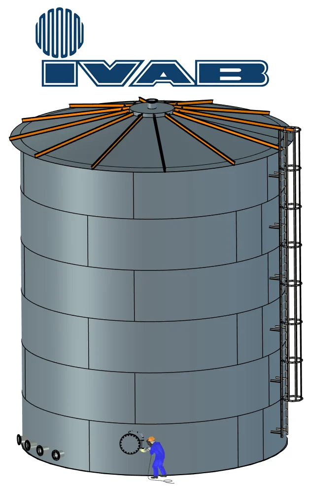
IVAB renovates and builds storage tanks and pressure vessels, with the entire design in a single file.
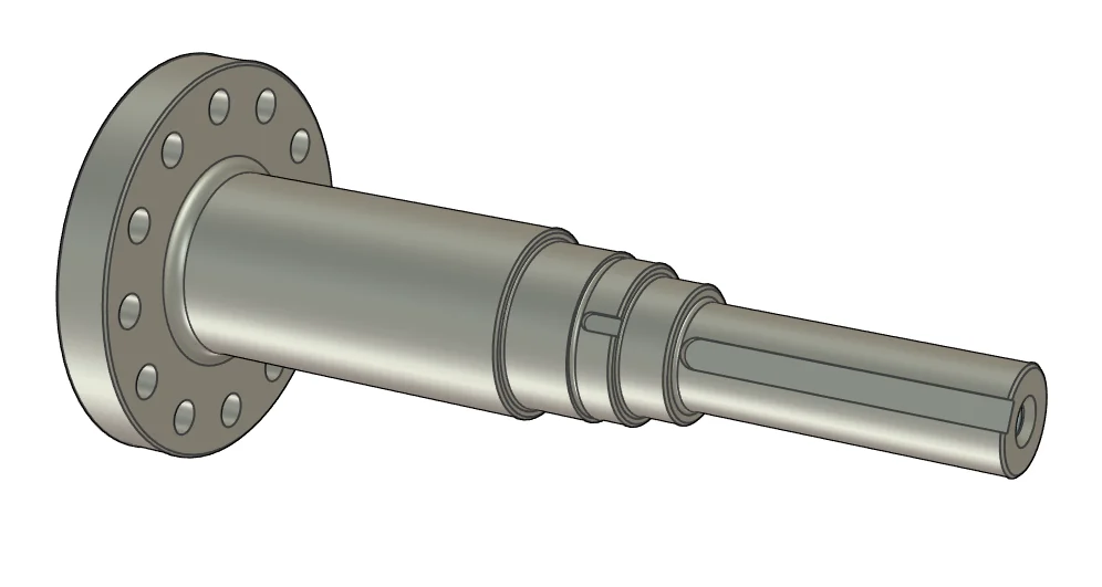
A worn-out shaft journal, gear, or mounting bracket for which no drawing is available can be measured and modeled in half an hour. A turning drawing with tolerances and surface finish specifications is generated from the model.
The next time that same machine breaks down, the part will already be in the catalog.
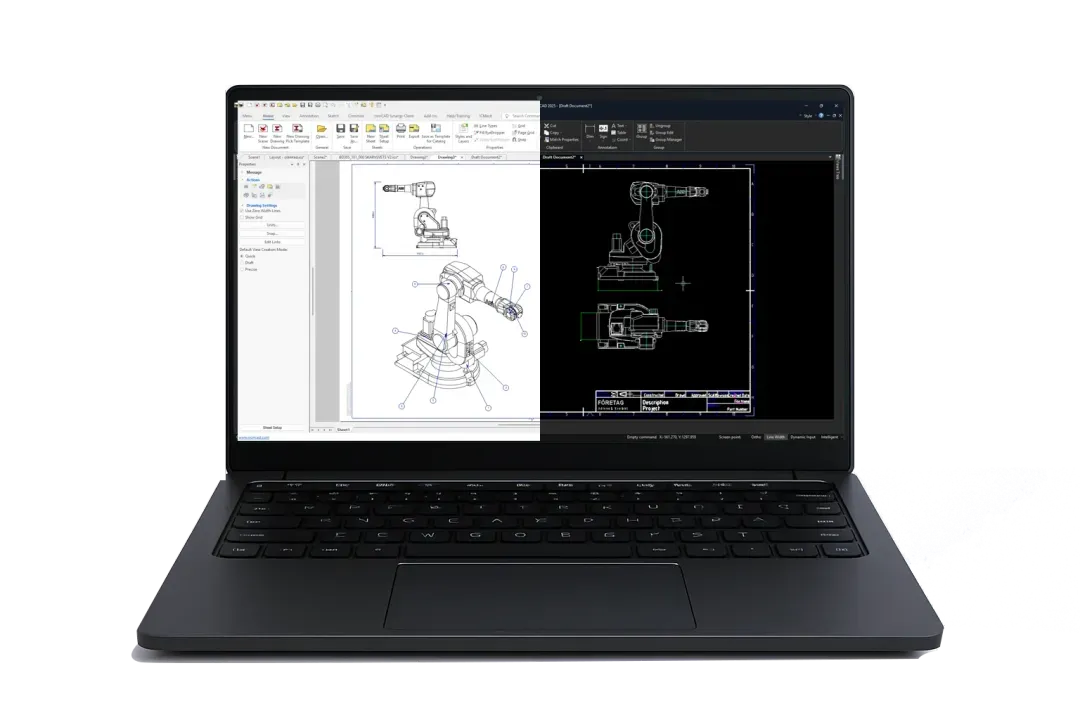
ICD depicts the fastener or conveyor using views, sections, ISO-compliant dimensions, and an automatic bill of materials. DRAFT features a traditional 2D interface similar to AutoCAD and opens the customer’s DWG and DXF files.
Both follow the same procedure when a customer calls to request a change. Choose the one that fits the drawing, or use both.
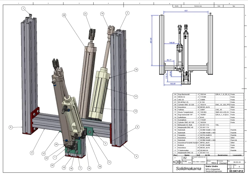
The assembly drawing is automatically assigned a part number and a bill of materials with item numbers, quantities, and suppliers. The detail drawings are dimensioned according to ISO standards, including tolerances.
The drawing is saved as a PDF and exported to DWG or DXF, so that the workshop and the customer have the same documentation.

Tanks, hatches, and protective covers made of bent sheet metal, including dimensions and DXF files.
The measurement is sketched freely in 2D. Set parameters whenever you want—it's not mandatory.

Standard components and custom, reusable solutions using drag-and-drop.

Position the mount precisely against the customer's equipment, without any constraints.

Over 50 years of experience in sheet metal fabrication, welding, laser cutting, and punching in Merlänna. Customers’ DWG, STEP, and SolidWorks files are opened in IRONCAD and converted into manufacturing files and cost estimates.

“We use IRONCAD for all aspects of manufacturing in our workshop. We design, create manufacturing files, and generate files for calculating component costs.”
Kennet Rodin, Production Manager, Länna Svets & Mekaniska Verkstad AB
Machining, repairs, and welding of large machine parts since 1950, with turning capabilities up to 13 meters. IRONCAD is used for sheet metal structures, steel frames, cutting files, and parts for chain conveyors.
“IRONCAD is a convenient tool for us that allows us to design and create manufacturing documentation for our production quickly and easily. It also gives us the ability to visually present different solutions to our customers.”
Magnus Andersson, Production Technician, Saltängens Mekaniska Verkstad AB
Infjärdens Värme in Piteå: turnkey contracting services in HVAC, industrial, workshop, and sprinkler systems, with eleven branches and 300 employees. Tanks, pressure vessels, pipe structures, and industrial repairs are manufactured at IRONCAD.

“Saving time is an important factor, and in this regard, IRONCAD is in a class of its own. Many steps in other programs are unnecessary and aren’t needed in IRONCAD.”
Patrik Ehlin, Project Manager, IVAB

Parts are imported directly into the assembly without separate part files, constraints, or history trees. A new mounting bracket or a modified conveyor can be designed in a matter of hours, and changes are made directly in 3D as soon as the customer calls.
Yes. DWG and DXF files are opened in DRAFT and used as the basis for the 3D model, and STEP or SolidWorks files of existing equipment are imported and used as a starting point. An on-site measurement can be sketched out in minutes.
Yes. IC Mechanical contains beams, pipes, bolted joints, ball bearings, packing boxes, lock rings, wedges, and pipe fittings in accordance with the standard. The parts are imported into the model and appear in the bill of materials with the correct designation.
The drawing is generated from the model, complete with dimensions, a parts list, and a DXF file for laser cutting, often on the same day the order is received. If the model is modified, the drawing is updated automatically.
Yes. With the free viewer at COMPOSE , the 3D model and drawing open on a laptop or tablet, allowing the installer to rotate, measure, and check the parts on site without a CAD license.
With Design Data Manager, every fastener, shaft, and drawing is assigned a part number, revision, and searchable properties—regardless of whether the file comes from IRONCAD, SolidWorks, or Inventor. When a customer calls about the same machine again, you can find the correct revision right away.
Full version for 30 days, free of charge. Swedish support and training from Solidmakarna.

30-day full version of IRONCAD . No credit card information required, no obligation to purchase.

Install the software, open your own files, and follow the setup wizard in the IronCAD Academy.

We'll show you how IRONCAD fits your specific production needs—in just half an hour.

A 2 + 2-day instructor-led introductory course, or self-paced study. Course instructors who design their own projects in IRONCAD.