Looks like you don't have ESC button on your device
Choose one of the following options
trial versionHas a license

Looks like you don't have ESC button on your device
Choose one of the following options
trial versionHas a licenseIRONCAD is a comprehensive 3D CAD program. In the sheet metal shop, it is used for 3D bending, unfolding customer files, and sending DXF files to the laser cutter and press brake, using drawings from the same model.
Over 1000+ satisfied customers



Customer files are expanded without history
Bending Radius and K-Factor per Sheet
DXF to the laser with one click
IRONCAD IRONCAD is a 3D CAD program for industrial design, ranging from machinery and sheet metal to layouts and fixtures. What sets apart from traditional CAD systems is the freedom of choice: you decide for yourself how to model. Design freely using drag-and-drop and TriBall, add constraints and parametric dimensions only where they’re needed, and modify imported geometry directly without a history tree. These methods can be combined within the same , and the entire assembly is contained in a single file. This page shows how sheet metal shops use it. part
The video demonstrates how a complex sheet metal part is built in IRONCAD using drag-and-drop: the geometry is shaped by dragging, pushing, and moving directly in 3D, using sheet metal tools such as miter cuts in combination with TriBall and the catalogs. When the part is complete, it is flattened with a single click and exported with bend lines, ready for laser cutting and press braking. Every change made in 3D is automatically reflected in the 2D drawing. The video is in English, from IronCAD Europe. Would you like to see what your next sheet metal part would look like in IRONCAD?
Book a demo and we’ll show you!
You select the method for each part, not for each program.
All three work in the same file, and they can be combined in a single 3D model.
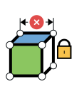
For enclosures and boxes that require variant management. Lock the length, width, and sheet metal thickness using constraints; the next size will then be recalculated based on the dimensions.
MOST POPULAR

The standard method in the sheet metal shop. Bend in 3D, drag the handles, and move holes with TriBall when the customer changes their mind. No restrictive constraints.
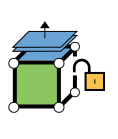
For the customer's STEP, SolidWorks, and Inventor files. Select a surface and drag it, change the hole diameter, convert to sheet metal, and unfold. No history is required.
SolidWorks, Inventor, STEP, or DXF—it doesn't matter. The part is opened, converted to sheet metal, and unfolded using the shop's own bend radii and K-factors, even when the file lacks a history.
Change the hole diameter directly in the imported geometry, without having to rebuild anything. With feature recognition during import , the holes and bends become actual features that can be edited.
Draw lines on the flat sheet metal where the bends will be located, specify the angle and radius for each line, and bend the sheet. The lines are adjusted using handles in 3D. Or extrude the cross-section from a 2D sketch. Both methods produce the same sheet metal part with the same footprint.
Sheet metal folded between two cross-sections creates transition pieces, cones, and radially bent parts. You choose how many bends the shape should be divided into. The angle for each bend is automatically displayed on the drawing, and the layout is sent as a DXF file to the laser cutter.
The sheet metal catalog is located next to the screen. Draw in ribs, die cuts, holes, and slots on the sheet metal and enter dimensions freely or from a table. The shapes are optimized for die cutting, shearing, and laser cutting, and are included in the unfolded layout.
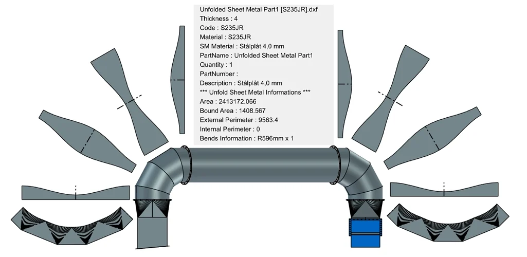
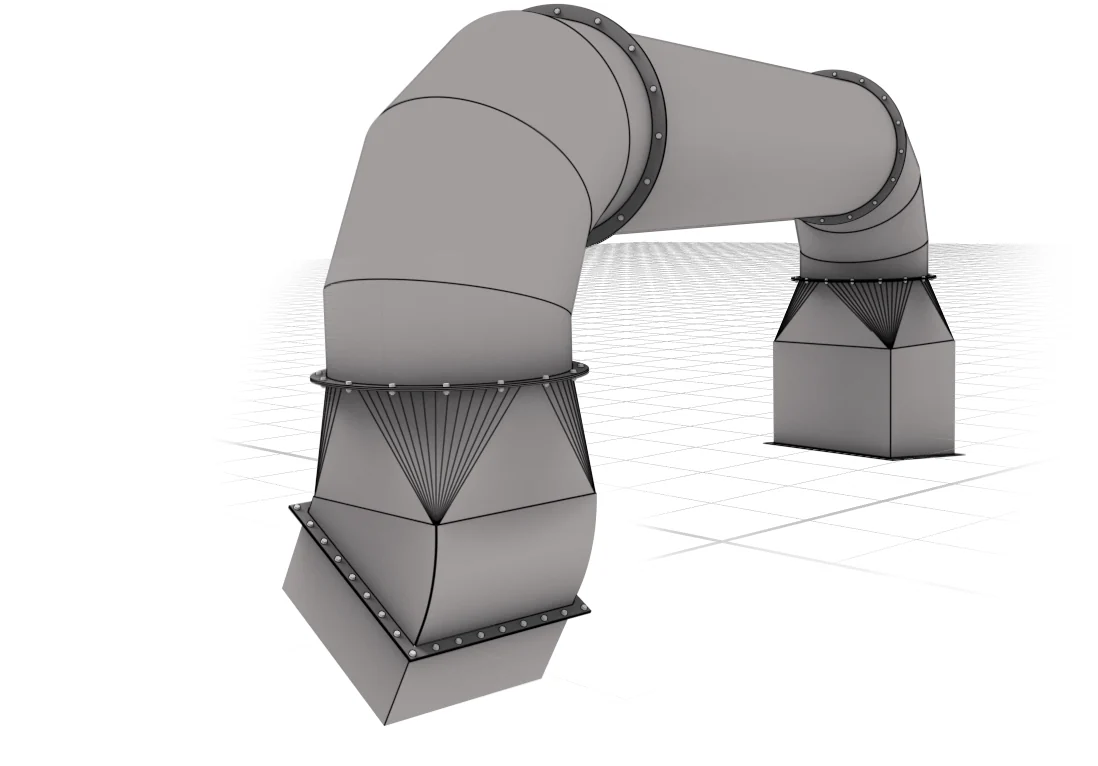
Face to DXF exports the correct surface with the correct layers, so that the laser receives separate cutting contours, engravings, and bend markings. Material, thickness, area, and bend information are included in the file. The example is IVAB’s ventilation elbow: twelve spread-out segments, exported with the click of a button.
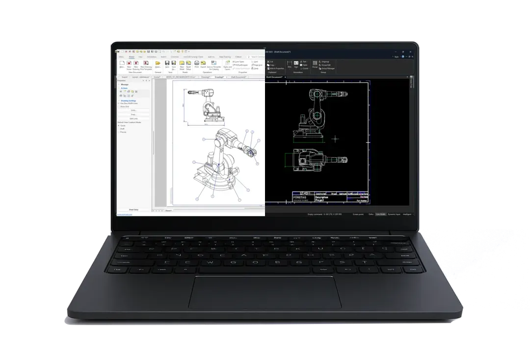
ICD displays the sheet metal part in both a bent and unfolded view, showing bend angles and the bending sequence for the press brake, with dimensions specified according to ISO. DRAFT features a traditional 2D interface similar to AutoCAD and can open and save the customer’s DWG and DXF files. Both update the model when the sheet metal is modified. Choose the one that best suits your drawing, or use both.

The enclosure, the frame made of IC profiles Mechanical, the fan grille, and the bolted joints are all in the same file as the sheet metal parts. The drawing with the bill of materials is generated from the model. The example is a dehumidifier that Länna Svets designed for AirWaterGreen, rendered in KeyShot for the customer’s presentation.

Bending, lofting, sheet metal table, unfolding, and Face to DXF.
Cross-sections and bend lines are drawn freely in 2D. Use parameters whenever you want—they’re not mandatory.

Custom machine modules and standard parts with drag-and-drop functionality.

Move, copy, and align parts precisely, without constraints.

Over 50 years of experience in sheet metal fabrication, welding, laser cutting, and punching in Merlänna. IRONCAD for 20 years for design, manufacturing files, and cost estimates.
“We use IRONCAD for all aspects of manufacturing in our workshop. We design, create manufacturing files, and generate files for calculating component costs.”
Kennet Rodin, Production Manager, Länna Svets & Mekaniska Verkstad AB
Machining, repairs, and welding of large structures since 1950. IRONCAD is primarily used for sheet metal fabrication, spreading, and cutting.

“IRONCAD is a convenient tool for us that allows us to design and create manufacturing documentation for our production quickly and easily.”
Magnus Andersson, production technician, Saltängens Mekaniska Verkstad AB
Infjärdens Värme in Piteå: HVAC, industrial, tanks and pressure vessels, 300 employees, and eleven branches. Ventilation pipes and conical reducers are rolled out at IRONCAD and cut using a laser.

“Saving time is an important factor, and in this regard, IRONCAD is in a class of its own. Many steps in other programs are unnecessary and aren’t needed in IRONCAD.”
Patrik Ehlin, Project Manager, IVAB

Yes. Imported sheet metal parts—from SolidWorks, Inventor, or STEP—are recognized as sheet metal and are unfolded using your bend radii and K-factors, even when the file lacks a history. This is the most common reason why sheet metal shops choose IRONCAD.
With Face to DXF, you select which surface to export and which lines go on which layer, so that the laser can process the cut outline, engraving, and bend marks separately. The export is done directly from the 3D model.
Yes. The sheet metal table at IRONCAD lists the thickness, bend radius, and K-factor for each material and tool, so that the bend specifications match those of your press brake. The table can be shared among all designers.
Yes. Sheet metal folded between two cross-sections creates transition pieces, cones, and flanged details that are expanded using bend lines for each segment. IVAB designs large ventilation ducts this way.
This page explains how a sheet metal shop works with customer files, lasers, and press brakes in IRONCAD. The "Sheet Metal" page under "Features" describes the tools in detail: Sketched Bend, Loft, the Sheet Metal Table, and Face to DXF.
With Design Data Manager, every customer file, sheet metal part, drawing, and DXF file is assigned a part number, revision, and searchable properties—regardless of whether the file comes from IRONCAD, SolidWorks, or Inventor. The laser and press brake always receive the correct revision.
Full version for 30 days, free of charge. Swedish support and training from Solidmakarna.

30-day full version of IRONCAD . No credit card information required, no obligation to purchase.

Install the software, open your own files, and follow the setup wizard in the IronCAD Academy.

We'll show you how IRONCAD fits your specific production needs—in just half an hour.

A 2 + 2-day instructor-led introductory course, or self-paced study. Course instructors who design their own projects in IRONCAD.